COMPUTER NETWORKS – USA20502J
UNIT
1
Computer
Networks
A computer network, also referred to as a data
network, is a series of
interconnected nodes that can transmit, receive and exchange data, voice and
video traffic. Examples of nodes in a network include servers or modems.
Computer networks commonly help endpoint users share resources and communicate.
Two or more computers connected that allows
sharing their data, resources, and application is called a computer network.
The vital computer network is divided into four types based on their size and
functions. They are LAN, MAN, PAN, and WAN.
Evolution of Networks
Advancement of systems
administration began path back in 1969’s by the improvement of first system
called ARPANET, which prompted the improvement of web. At that point after
constantly everyday upgradation occur in the system innovation. The system has
gone through a few phases which are described below:
ARPANET (Advanced Research
Agency Network):
ARPANET was the network that
became the basis for the Internet. It was the first network that came into
existence in 1969, which was designed and named by the Advanced Research
Projects Agency (ARPA) and US Department of Defence (DoD). It was where a bunch
of PCs were associated at various colleges and US DoD for sharing of
information and messages and playing long separation diversions and associating
with individuals to share their perspectives.
NSFNET (National Science
Federation Network):
In mid 80’s another federal agency,
NSFNET (National Science Federation Network) created a new network which was
more capable than ARPANET and became the first backbone infrastructure for the
commercial public Internet.
ARPANET + NSFNET +
PRIVATE NETWORKS = INTERNET

The
Internet:
The Internet provides different online services. Some
examples include: Web – a collection of billions of webpages that you can view
with a web browser. Email – the most common method of sending and receiving
messages online. Social media – websites and apps that allow people to share
comments, photos, and videos.
In
the Internet, which is a network of networks, came into existence. The internet
has evolved from ARPANET. The internet is a globally connected network system
that utilizes TCP/IP to transmit information. It allows computers of different
types to exchange information and is known as internet. The Internet is the
financially communications method on the planet, in which the following
services are instantly available
·
Email
·
Web-enabled
audio/video conferencing services
·
Online movies and
gaming
·
Data
transfer/file-sharing, often through File Transfer Protocol (FTP)
·
Instant messaging
·
Internet forums
·
Social networking
·
Online shopping
·
Financial
services
Interspace:
Interspaces is a software that allows multiple users in a client-server
environment to communicate with each other to send and receive data of various
types such as data files, video, audio and textual data. Interspaces give the
most exceptional type form of communication available on the Internet today.
Data Communication:
The term
telecommunication means communication at a distance. The word data refers to
information presented in whatever form is agreed upon by the parties creating
and using the data. Data communications are the exchange of data between two
devices via some form of transmission medium such as a wire cable
Components
of a data communications system

5 components of data communication network
Ø
Data.
Ø
Sender.
Ø
Receiver.
Ø
Transmission Medium.
Ø
Protocol.
1.
Message:
·
The message is the information (data) to be
communicated. Popular forms of information include text, numbers, pictures,
audio, and video.
2. Sender:
·
The sender is the device that sends the data
message. It can be a computer, workstation, telephone handset, video camera,
and so on.
3. Receiver:
·
The receiver is the device that receives the
message. It can be a computer, workstation, telephone handset, television, and
so on.
4. Transmission medium:
·
The transmission medium is the physical path
by which a message travels from sender to receiver. Some examples of
transmission media include twisted-pair wire, coaxial cable, fiber-optic cable,
and radio waves.
5. Protocol:
·
A protocol is a set of rules that govern data
communications. It represents an agreement between the communicating devices.
Without a protocol, two devices may be connected but not communicating, just as
a person speaking French cannot be understood by a person who speaks only
Japanese.
Data flow (simplex, half-duplex, and full-duplex)

Networks
A
network is a set of devices (often referred to as nodes) connected by
communication links. A node can be a computer, printer, or any other device
capable of sending and/or receiving data generated by other nodes on the
network. A link can be a cable, air, optical fiber, or any medium which can
transport a signal carrying information.
A network is a collection of computers, servers,
mainframes, network devices, peripherals, or other devices connected to allow
data sharing. An example of a network is the Internet, which connects
millions of people all over the world.

Network Criteria
Ø Performance
I.
Depends on Network Elements
II.
Measured in terms of Delay and Throughput
Ø Reliability
I.
Failure rate of network components
II.
Measured in terms of availability/robustness
Ø Security
I.
Data protection against corruption/loss of data due
to:
II.
Errors
Physical
Structures
Ø
Type of Connection
I.
Point to Point - single transmitter and receiver
II.
Multipoint - multiple recipients of single
transmission
Ø
Physical
Topology
I.
Connection of devices
II.
Type of transmission - unicast, mulitcast, broadcast
Categories of Networks
PERSONAL
AREA NETWORK (PAN) ...
This is the smallest and most basic network that you’ll
find. It’s meant to cover a very small area (typically a single room or
building).
LOCAL
AREA NETWORK (LAN) ...
This is an extremely common and well-known type of
network. Just as the name suggests, a LAN connects a group of computers or
devices together across a local area. This type of network can be utilized to
connect devices throughout one building or even 2-3 buildings depending on the
proximity to each other
WIRELESS
LOCAL AREA NETWORK (WLAN) .
A WLAN is simply a LAN that does not rely on cables to
connect to the network. So, when you’re using WiFi, you’re using a WLAN. WLANs
are typically used in the same scenario as LANs, it just depends on whether
you’d prefer an on premises or remote cloud solution (wires or wireless)...
METROPOLITAN
AREA NETWORK (MAN) ...
Larger than a LAN but smaller than a WAN, a MAN
incorporates elements of both types of networks. It connects multiple LANs
together and spans an entire geographical area such as a city or town (or
sometimes a campus). Ownership and management can be handled by a single
person, but it’s more likely done by a larger company or organization.
WIDE
AREA NETWORK (WAN) ...
Like LANs, you very well may recognize the term “WAN.”
WANs do the same thing as LANs but across a larger area while connecting more
devices. Even when miles apart, a WAN can connect devices together remotely. In
fact, the most basic example of a WAN is the Internet which connects computers
and devices worldwide.
STORAGE
AREA NETWORK (SAN) ...
A SAN is another type of LAN that’s designed to handle
large data transfers and storage. This purpose of this network is to move
larger, more complex storage resources away from the network into a separate,
high-performance atmosphere. Doing this not only allows for easy retrieval and
storage of the data but it also frees up space and improves overall performance
of the original network.
VIRTUAL
PRIVATE NETWORK (VPN)
The point of a VPN is to
increase security and privacy while accessing a network. The VPN acts as a
middleman between you and the network by encrypting your data and hiding your
identity. This is a great option for sending and receiving sensitive
information, however, using a VPN is ideal anytime you connect to the
Internet.
Types of
connections: point-to-point and multipoint

Types of topologies
Ø Bus Topology.
Ø Ring Topology.
Ø Star Topology.
Ø Mesh Topology.
Ø Tree Topology.
Ø Hybrid Topology.

Protocols
A protocol is synonymous with rule. It consists of a set of rules that
govern data communications. It determines what is communicated, how it is
communicated and when it is communicated. The key elements of a protocol are
syntax, semantics and timing
Elements of a
Protocol
n Syntax
n Structure or format
of the data
n Indicates how to read
the bits - field delineation
n Semantics
n Interprets the
meaning of the bits
n Knows which fields
define what action
n Timing
n When data should be
sent and what
n Speed at which data
should be sent or speed at which it is being received.
Network Models

OSI NETWORK MODEL (Open Systems Interconnection)
Layers of OSI Model
OSI stands for Open Systems Interconnection. It has
been developed by ISO – ‘International Organization for Standardization‘, in
the year 1984. It is a 7 layer architecture with each layer having specific
functionality to perform. All these 7 layers work collaboratively to transmit
the data from one person to another across the globe


LAYER Wise Protocols
1. Physical Layer
(Layer 1) :
The lowest layer of the OSI reference model is the physical
layer. It is responsible for the actual physical connection between the
devices. The physical layer contains information in the form of bits. It is responsible for
transmitting individual bits from one node to the next. When receiving data,
this layer will get the signal received and convert it into 0s and 1s and send
them to the Data Link layer, which will put the frame back together.
The functions of the physical
1.
Bit synchronization: The physical
layer provides the synchronization of the bits by providing a clock. This clock
controls both sender and receiver thus providing synchronization at bit level.
2.
Bit rate control: The Physical
layer also defines the transmission rate i.e. the number of bits sent per
second.
3.
Physical topologies: Physical layer
specifies the way in which the different, devices/nodes are arranged in a
network i.e. bus, star, or mesh topology.
4.
Transmission mode: Physical layer
also defines the way in which the data flows between the two connected devices.
The various transmission modes possible are Simplex, half-duplex and
full-duplex.

Data Link Layer (DLL)
(Layer 2) :
The data link layer is
responsible for the node-to-node delivery of the message. The main function of
this layer is to make sure data transfer is error-free from one node to
another, over the physical layer. When a packet arrives in a network, it is the
responsibility of DLL to transmit it to the Host using its MAC address.
Data Link Layer is divided into two sublayers:
1.
Logical Link Control (LLC)
2.
Media Access Control (MAC)
The functions of the Data Link layer
1.
Framing: Framing is a function
of the data link layer. It provides a way for a sender to transmit a set of
bits that are meaningful to the receiver. This can be accomplished by attaching
special bit patterns to the beginning and end of the frame.
2.
Physical addressing: After creating
frames, the Data link layer adds physical addresses (MAC address) of the sender
and/or receiver in the header of each frame.
3.
Error control: Data link layer
provides the mechanism of error control in which it detects and retransmits
damaged or lost frames.
4.
Flow Control: The data rate
must be constant on both sides else the data may get corrupted thus, flow
control coordinates the amount of data that can be sent before receiving
acknowledgement.
5.
Access control: When a single
communication channel is shared by multiple devices, the MAC sub-layer of the
data link layer helps to determine which device has control over the channel at
a given time.

3. Network Layer (Layer
3) :
The network layer works for the transmission of data from one
host to the other located in different networks. It also takes care of packet
routing i.e. selection of the shortest path to transmit the packet, from the
number of routes available. The sender & receiver’s IP addresses are placed
in the header by the network layer.
The functions of the Network layer
1.
Routing: The network
layer protocols determine which route is suitable from source to destination.
This function of the network layer is known as routing.
2.
Logical
Addressing: In order to identify each device on internetwork uniquely, the
network layer defines an addressing scheme. The sender & receiver’s IP
addresses are placed in the header by the network layer. Such an address
distinguishes each device uniquely and universally.
3. Internetworking: An internetworking is the main
responsibility of the network layer. It provides a logical connection between
different devices.
4. Packetizing: A Network Layer receives the packets from the upper layer
and converts them into packets. This process is known as Packetizing. It is
achieved by internet protocol (IP)

4. Transport Layer
(Layer 4) :
The transport layer provides services to the application layer
and takes services from the network layer. The data in the transport layer is
referred to as Segments. It is
responsible for the End to End Delivery of the complete message.
The transport layer also provides the acknowledgement of the
successful data transmission and re-transmits the data if an error is found.
At sender’s
side: Transport layer receives the formatted data from the upper
layers, performs Segmentation,
and also implements Flow &
Error control to ensure proper data transmission. It also adds Source
and Destination port numbers in its header and forwards the segmented data to
the Network Layer.
At receiver’s side: Transport Layer
reads the port number from its header and forwards the Data which it has
received to the respective application. It also performs sequencing and
reassembling of the segmented data.
The functions of the transport layer
1.
Segmentation and
Reassembly: This layer accepts the message from the (session) layer,
and breaks the message into smaller units. Each of the segments produced has a
header associated with it. The transport layer at the destination station
reassembles the message.
2.
Service Point
Addressing: In order to deliver the message to the correct process,
the transport layer header includes a type of address called service point
address or port address. Thus by specifying this address, the transport layer
makes sure that the message is delivered to the correct process.
The services provided by the transport layer
A. Connection-Oriented
Service: It
is a three-phase process that includes
–Connection
Establishment
–Data Transfer
– Termination / disconnection
In
this type of transmission, the receiving device sends an acknowledgement, back
to the source after a packet or group of packets is received. This type of
transmission is reliable and secure.
B. Connectionless
service: It
is a one-phase process and includes Data Transfer. In this type of
transmission, the receiver does not acknowledge receipt of a packet. This
approach allows for much faster communication between devices.
Connection-oriented service is more reliable than connectionless Service.

5. Session Layer (Layer
5) :
This layer is
responsible for the establishment of connection, maintenance of sessions,
authentication, and also ensures security
.
The functions of the session layer :
1.
Session establishment,
maintenance, and termination: The layer allows the two processes to
establish, use and terminate a connection.
2.
Synchronization: This layer
allows a process to add checkpoints which are considered synchronization points
into the data. These synchronization points help to identify the error so that
the data is re-synchronized properly, and ends of the messages are not cut
prematurely and data loss is avoided.
3.
Dialog Controller: The session
layer allows two systems to start communication with each other in half-duplex
or full-duplex.
 6. Presentation Layer (Layer 6):
The presentation layer is also called the Translation layer. The data from the
application layer is extracted here and manipulated as per the required format
to transmit over the network.
The functions of the
presentation layer
●
Translation: For example,
ASCII to EBCDIC.
●
Encryption/
Decryption: Data encryption translates the data into another form or
code. The encrypted data is known as the ciphertext and the decrypted data is
known as plain text. A key value is used for encrypting as well as decrypting
data.
●
Compression: Reduces the
number of bits that need to be transmitted on the network.
7. Application Layer
(Layer 7) :
At the very top of the OSI Reference Model stack of layers, we
find the Application layer which is implemented by the network applications.
These applications produce the data, which has to be transferred over the network. This layer also serves as a
window for the application services to access the network and for displaying
the received information to the user.
over the network. This layer also serves as a
window for the application services to access the network and for displaying
the received information to the user.
Example: Application –
Browsers, Skype Messenger, etc.
The functions of the Application layer are
:
1.
Network Virtual Terminal
2.
FTAM-File transfer access and management
3.
Mail Services
4.
Directory Services

TCP/IP
model
- The
TCP/IP model was developed prior to the OSI model.
- The
TCP/IP model is not exactly similar to the OSI model.
- The
TCP/IP model consists of five layers: the application layer, transport
layer, network layer, data link layer and physical layer.
- The
first four layers provide physical standards, network interface,
internetworking, and transport functions that correspond to the first four
layers of the OSI model and these four layers are represented in TCP/IP
model by a single layer called the application layer.
- TCP/IP
is a hierarchical protocol made up of interactive modules, and each of
them provides specific functionality.
Here, hierarchical means that each upper-layer protocol is
supported by two or more lower-level protocols.
Functions
of TCP/IP layers:

Network
Access Layer
- A
network layer is the lowest layer of the TCP/IP model.
- A
network layer is the combination of the Physical layer and Data Link layer
defined in the OSI reference model.
- It
defines how the data should be sent physically through the network.
- This
layer is mainly responsible for the transmission of the data between two
devices on the same network.
- The
functions carried out by this layer are encapsulating the IP datagram into
frames transmitted by the network and mapping of IP addresses into
physical addresses.
- The
protocols used by this layer are ethernet, token ring, FDDI, X.25, frame
relay.
Internet
Layer
- An
internet layer is the second layer of the TCP/IP model.
- An
internet layer is also known as the network layer.
- The
main responsibility of the internet layer is to send the packets from any
network, and they arrive at the destination irrespective of the route they
take.
Following are the
protocols used in this layer are:
IP Protocol: IP protocol is used in this layer, and
it is the most significant part of the entire TCP/IP suite.
Following are the responsibilities of this protocol:
- IP
Addressing: This
protocol implements logical host addresses known as IP addresses. The IP
addresses are used by the internet and higher layers to identify the
device and to provide internetwork routing.
- Host-to-host
communication: It
determines the path through which the data is to be transmitted.
- Data
Encapsulation and Formatting: An IP protocol accepts the data from the
transport layer protocol. An IP protocol ensures that the data is sent and
received securely, it encapsulates the data into message known as IP
datagram.
- Fragmentation
and Reassembly: The
limit imposed on the size of the IP datagram by data link layer protocol
is known as Maximum Transmission unit (MTU). If the size of IP datagram is
greater than the MTU unit, then the IP protocol splits the datagram into
smaller units so that they can travel over the local network.
Fragmentation can be done by the sender or intermediate router. At the
receiver side, all the fragments are reassembled to form an original
message.
- Routing: When IP datagram is sent
over the same local network such as LAN, MAN, WAN, it is known as direct
delivery. When source and destination are on the distant network, then the
IP datagram is sent indirectly. This can be accomplished by routing the IP
datagram through various devices such as routers.
ARP and RARP Protocols Java Program
Stay
- ARP
stands for Address Resolution Protocol.
- ARP
is a network layer protocol which is used to find the physical address
from the IP address.
- The
two terms are mainly associated with the ARP Protocol:
- ARP
request: When
a sender wants to know the physical address of the device, it broadcasts
the ARP request to the network.
- ARP
reply: Every
device attached to the network will accept the ARP request and process
the request, but only recipient recognize the IP address and sends back
its physical address in the form of ARP reply. The recipient adds the
physical address both to its cache memory and to the datagram header.
Reverse Address
Resolution Protocol (RARP)
is a protocol a physical machine in a local area
network (LAN) can use to request its IP address. It does this by sending
the device's physical address to a specialized RARP server that is on the same
LAN and is actively listening for RARP requests.
ICMP Protocol
- ICMP stands for Internet
Control Message Protocol.
- It
is a mechanism used by the hosts or routers to send notifications
regarding datagram problems back to the sender.
- A
datagram travels from router-to-router until it reaches its destination.
If a router is unable to route the data because of some unusual conditions
such as disabled links, a device is on fire or network congestion, then
the ICMP protocol is used to inform the sender that the datagram is
undeliverable.
- An
ICMP protocol mainly uses two terms:
- ICMP
Test: ICMP
Test is used to test whether the destination is reachable or not.
- ICMP
Reply: ICMP
Reply is used to check whether the destination device is responding or
not.
- The
core responsibility of the ICMP protocol is to report the problems, not
correct them. The responsibility of the correction lies with the sender.
- ICMP
can send the messages only to the source, but not to the intermediate
routers because the IP datagram carries the addresses of the source and
destination but not of the router that it is passed to.
IGMP
- The
Internet Group Management Protocol (IGMP) manages the membership
of hosts and routing devices in multicast groups. IP hosts use IGMP to
report their multicast group memberships to any immediately neighboring
multicast routing devices.
Transport
Layer
The transport layer is responsible for the reliability, flow
control, and correction of data which is being sent over the network.
The two protocols used in the transport layer are User
Datagram protocol and Transmission control protocol.
- User
Datagram Protocol (UDP)
- It
provides connectionless service and end-to-end delivery of transmission.
- It
is an unreliable protocol as it discovers the errors but not specify the
error.
- User
Datagram Protocol discovers the error, and ICMP protocol reports the
error to the sender that user datagram has been damaged.
UDP consists of the
following fields:
Source port address: The
source port address is the address of the application program that has created
the message.
Destination port address: The
destination port address is the address of the application program that
receives the message.
Total length: It defines
the total number of bytes of the user datagram in bytes.
Checksum: The checksum is a
16-bit field used in error detection.
UDP does not specify which packet is lost. UDP
contains only checksum; it does not contain any ID of a data segment.


Transmission Control Protocol (TCP)
o It provides a full
transport layer services to applications.
o It creates a virtual
circuit between the sender and receiver, and it is active for the duration of
the transmission.
o TCP is a reliable
protocol as it detects the error and retransmits the damaged frames. Therefore,
it ensures all the segments must be received and acknowledged before the
transmission is considered to be completed and a virtual circuit is discarded.
o At the sending end, TCP
divides the whole message into smaller units known as segment, and each segment
contains a sequence number which is required for reordering the frames to form
an original message.
o At the receiving end,
TCP collects all the segments and reorders them based on sequence numbers.
Application
Layer
- An
application layer is the topmost layer in the TCP/IP model.
- It
is responsible for handling high-level protocols, issues of
representation.
- This
layer allows the user to interact with the application.
- When
one application layer protocol wants to communicate with another
application layer, it forwards its data to the transport layer.
- There
is an ambiguity occurs in the application layer. Every application cannot
be placed inside the application layer except those who interact with the
communication system. For example: text editor cannot be considered in
application layer while web browser using HTTP protocol
to interact with the network where HTTP protocol is an
application layer protocol.
Following
are the main protocols used in the application layer:
- HTTP: HTTP stands for Hypertext
transfer protocol. This protocol allows us to access the data over the
world wide web. It transfers the data in the form of plain text, audio,
video. It is known as a Hypertext transfer protocol as it has the
efficiency to use in a hypertext environment where there are rapid jumps
from one document to another.
- SNMP: SNMP stands for Simple
Network Management Protocol. It is a framework used for managing the
devices on the internet by using the TCP/IP protocol suite.
- SMTP: SMTP stands for Simple
mail transfer protocol. The TCP/IP protocol that supports the e-mail is
known as a Simple mail transfer protocol. This protocol is used to send
the data to another e-mail address.
- DNS: DNS stands for Domain
Name System. An IP address is used to identify the connection of a host to
the internet uniquely. But, people prefer to use the names instead of
addresses. Therefore, the system that maps the name to the address is
known as Domain Name System.
- TELNET: It is an abbreviation for
Terminal Network. It establishes the connection between the local computer
and remote computer in such a way that the local terminal appears to be a
terminal at the remote system.
- FTP: FTP stands for File
Transfer Protocol. FTP is a standard internet protocol used for
transmitting the files from one computer to another computer.
Peer to Peer Approach
A peer-to-peer network is designed around the notion of equal peer nodes simultaneously functioning
as both "clients" and "servers" to the other nodes on the
network. This model of network arrangement differs from the
client–server model where communication is usually to and from a central
server.
Types of P2P networks:
1.
Unstructured P2P networks –
In this type of P2P network, each device is able to make an equal contribution.
This network is easy to build as devices can be connected randomly in the
network. But being unstructured, it becomes difficult to find content.
2.
Structured P2P networks –
It is designed using the software which creates a virtual layer in order to put
the nodes in a specific structure. These are not easy to set-up but can give
easy access to users to the content.
3.
Hybrid P2P networks –
It combines the features of both P2P network and client-server architecture. An
example of such a network is to find a node using the central server.

Advantages of P2P Network
:
·
Network is easy to maintain because each
node is independent of each other.
·
Since each node acts as a server, therefore
the cost of the central server is saved.
·
Adding, deleting and repairing nodes in this
network is easy.
Disadvantages of P2P
Network :
·
Because of no central server, data is always
vulnerable to get lost because of no backup.
·
It becomes difficult to secure the complete
network because each node is independent.
UNIT -2
Network Addressing
A computer network is a group of some interconnected computers that are
sharing a common or different resources provided on or by network nodes. These
sharing or communication between the machines is governed by some set of rules
or network protocols. These
computers or machines are identified by network addresses, and may have
hostnames.
A Network Address is a
logical or physical address that uniquely identifies a host or a machine in a
telecommunication network. A network may also not be unique and can contain
some structural and hierarchical information of the node in the network.
Internet protocol (IP) address, media access control (MAC) address and
telephone numbers are some basic examples of network addresses. It can be of
numeric type or symbolic or both in some cases.

Four types of addressing methods used are the
following:
§
Physical address
§
Logical address (IP)
§
Port address and
§
Specific address
Four levels of
addresses are used in the TCP/IP protocol: physical address,
logical address, port address, and application-specific address as
shown in Figure.

MAC
Addresses (Physical Address)
- The physical address, also known as the
link address, is the address of a node as defined by its LAN or WAN.
- The size and
format of these addresses vary depending on the network. For example,
Ethernet uses a 6-byte (48-bit) physical address.
- Physical addresses
can be either unicast (one single recipient), multicast (a group of
recipients), or broadcast (to be received by all systems in the network.
- Example: Most
local area networks use a 48-bit (6-byte) physical address written as 12
hexadecimal digits; every byte (2 hexadecimal digits) is separated by a
colon, as shown below: A 6-byte (12 hexadecimal digits) physical
address 07:01:02:01:2C:4B
Logical Addresses ((IP Addresses)
- Logical addresses
are used by networking software to allow packets to be independent of the
physical connection of the network, that is, to work with different
network topologies and types of media.
- A logical address
in the Internet is currently a 32-bit address that can uniquely define a
host connected to the Internet. An internet address in IPv4 in decimal
numbers 132.24.75.9
- No two publicly
addressed and visible hosts on the Internet can have the same IP address.
- The physical
addresses will change from hop to hop, but the logical addresses remain
the same.
- The logical
addresses can be either unicast (one single recipient), multicast (a group
of recipients), or broadcast (all systems in the network). There are
limitations on broadcast addresses.
Port Addresses
- There are many
application running on the computer. Each application run with a port
no.(logically) on the computer.
- A port number is
part of the addressing information used to identify the senders and
receivers of messages.
- Port numbers are
most commonly used with TCP/IP connections.
- These port numbers
allow different applications on the same computer to share network
resources simultaneously.
- The physical
addresses change from hop to hop, but the logical and port addresses
usually remain the same.
- Example: a port address
is a 16-bit address represented by one decimal number 753
Application-Specific
Addresses
- Some applications
have user-friendly addresses that are designed for that specific
application.
- Examples include
the e-mail address (for example, forouzan@fhda.edu) and the Universal
Resource Locator (URL) (for example, www.mhhe.com). The first defines the
recipient of an e-mail; the second is used to find a document on the World
Wide Web.
IPv4 addresses
IPv4 addresses are 32-bit numbers that are typically displayed
in dotted decimal notation. A 32-bit address contains two primary parts:
the network prefix and the host number. All hosts within a single network share
the same network address. Each host also has an address that uniquely
identifies it.
IP (version 4) addresses are 32-bit
integers that can be expressed in hexadecimal notation. The more common format,
known as dotted quad or dotted decimal, is x.x.x.x, where each x can be any
value between 0 and 255. For example, 192.0. 2.146 is
a valid IPv4 address.
IP stands
for Internet Protocol and v4 stands for Version Four (IPv4). IPv4 was the primary
version brought into action for production within the ARPANET in 1983.
IP version four addresses are 32-bit
integers which will be expressed in decimal notation.
Example- 192.0.2.126 could be an IPv4 address.

Parts of IPv4
·
Networkpart:
The network part indicates the distinctive variety that’s appointed to the
network. The network part conjointly identifies the category of the network
that’s assigned.
·
HostPart:
The host part uniquely identifies the machine on your network. This part of the
IPv4 address is assigned to every host.
For each host on the network, the network part is the same, however, the host
half must vary.
·
Subnet number:
This is the nonobligatory part of IPv4. Local networks
that have massive numbers of hosts are divided into subnets and subnet numbers
are appointed to that.
Characteristics of IPv4
·
IPv4 could be a 32-Bit IP Address.
·
IPv4 could be a numeric address, and its bits are
separated by a dot.
·
The number of header fields is twelve and the length of
the header field is twenty.
·
It has Unicast, broadcast, and multicast style of
addresses.
·
IPv4 supports VLSM (Virtual Length Subnet Mask).
·
IPv4 uses the Post Address Resolution Protocol to map to
the MAC address.
·
RIP may be a routing protocol supported by the routed
daemon.
·
Networks ought to be designed either manually or with
DHCP.
·
Packet fragmentation permits from routers and causing
host.
Advantages of IPv4
·
IPv4 security permits encryption to keep up privacy and
security.
·
IPV4 network allocation is significant and presently has
quite 85000 practical routers.
·
It becomes easy to attach multiple devices across an
outsized network while not NAT.
·
This is a model of communication so provides quality
service also as economical knowledge transfer.
·
IPV4 addresses are redefined and permit flawless encoding.
·
Limits net growth for existing users and hinders the use
of the net for brand new users.
·
Internet Routing is inefficient in IPv4.
·
IPv4 has high System Management prices and it’s
labor-intensive, complex, slow & frequent to errors.
·
Security features are nonobligatory.
·
Difficult to feature support for future desires as a
result of adding it on is extremely high overhead since it hinders the
flexibility to attach everything over IP.
There
are four different types of IP addresses: public, private,
static, and dynamic.
Internet Protocol hierarchy contains several
classes of IP Addresses to be used efficiently in various situations as per the
requirement of hosts per network. Broadly, the IPv4 Addressing system is divided into
five classes of IP Addresses. All the five classes are identified by the first
octet of IP Address.
Internet Corporation for
Assigned Names and Numbers is responsible for assigning IP addresses.
The first octet referred here is the left most
of all. The octets numbered as follows depicting dotted decimal notation of IP
Address −

The number of networks and the number of hosts per class can be
derived by this formula −

When calculating hosts' IP addresses, 2 IP
addresses are decreased because they cannot be assigned to hosts, i.e. the
first IP of a network is network number and the last IP is reserved for
Broadcast IP.
Network
Addressing:
It is the prime responsibility of the network layer to
assign unique addresses to different nodes in a network. As mentioned earlier
they can be physical or logical but primarily they are logical addresses i.e.
software-based addresses. The most widely used network address is an IP
address. It uniquely identifies a node in an IP network.
An IP address is a 32-bit long numeric address represented
in a form of dot-decimal notation where each byte is written in a decimal form
separated by a period. For example 196.32.216.9 is an IP address where 196
represents first 8 bits, 32 next 8 bits and so on. The first three bytes of an
IP address represents the network and the last byte specifies the host in the
network. An IP address is further divided into sub classes
Classful Addressing:
Classful
addressing is an IPv4 addressing architecture that divides addresses into five
groups.
Prior to classful addressing, the first eight
bits of an IP address defined the network a given host was a part of. This
would have had the effect of limiting the internet to just 254 networks. Each
of those networks contained 16,777,216 different IP addresses. As the internet
grew, the inefficiency of allocating IP addresses this way became a problem.
After all, there are a lot more than 254 organizations that need IP addresses,
and a lot fewer networks that need 16.7 million IP addresses to themselves.
·
Class A : An IP address is assigned to those networks that include
large number of hosts.
·
Class B : An IP address is assigned to networks range from small
sized to large sized.
·
Class C : An IP address is assigned to networks that are small
sized.
·
Class D : IP address are reserved for multicast address and does not
possess subnetting.
·
Class E : An IP address is used for the future use and for the
research and development purposes and does not possess any subnetting.
An IP address is divided
into two parts:
1.
Network ID : represents the number of networks.
2.
Host ID : represents the number of hosts
.

In
the above diagram, we observe that each class have a specific range of IP
addresses. The class of IP address is used to determine the number of bits used
in a class and number of networks and hosts available in the class.
Class A
In Class A, an IP address is assigned to those networks that contain a
large number of hosts.
- The network ID is
8 bits long.
- The host ID is 24
bits long.
In Class A, the first bit in higher order bits of the first octet is
always set to 0 and the remaining 7 bits determine the network ID. The 24 bits
determine the host ID in any network.
The
total number of networks in Class A = 27 = 128 network address
The
total number of hosts in Class A = 224 - 2 = 16,777,214 host
address

Class B
In Class B, an IP address is assigned to those networks that range from
small-sized to large-sized networks.
- The Network ID is
16 bits long.
- The Host ID is 16
bits long.
In Class B, the higher order bits of the first octet is always set to
10, and the remaining14 bits determine the network ID. The other 16 bits
determine the Host ID.
The
total number of networks in Class B = 214 = 16384 network
address
The
total number of hosts in Class B = 216 - 2 = 65534 host address

Class C
In Class C, an IP address is assigned to only small-sized networks.
- The Network ID is 24 bits long.
- The host ID is 8 bits long.
In Class C, the higher
order bits of the first octet is always set to 110, and the remaining 21 bits
determine the network ID. The 8 bits of the host ID determine the host in a
network.
The total number of networks = 221 =
2097152 network address
The total number of hosts = 28 -
2 = 254 host address

Class D
In
Class D, an IP address is reserved for multicast addresses. It does not possess
subnetting. The higher order bits of the first octet are always set to 1110,
and the remaining bits determine the host ID in any network.

Class E
In
Class E, an IP address is used for the future use or for the research and
development purposes. It does not possess any subnetting. The higher order bits
of the first octet is always set to 1111, and the remaining bits determines the
host ID in any network.

Rules for
assigning Host ID:
The Host ID is used to determine the host within any network. The Host
ID is assigned based on the following rules:
- The Host ID must
be unique within any network.
- The Host ID in
which all the bits are set to 0 cannot be assigned as it is used to
represent the network ID of the IP address.
- The Host ID in
which all the bits are set to 1 cannot be assigned as it is reserved for
the multicast address.
Rules for
assigning Network ID:
If the hosts are located within the same local network, then they are
assigned with the same network ID. The following are the rules for assigning
Network ID:
- The network ID
cannot start with 127 as 127 is used by Class A.
- The Network ID in
which all the bits are set to 0 cannot be assigned as it is used to
specify a particular host on the local network.
- The Network ID in
which all the bits are set to 1 cannot be assigned as it is reserved for
the multicast address.
Classful addressing works
Classful addressing
divides the IPv4 address space (0.0.0.0-255.255.255.255) into 5 classes: A, B,
C, D, and E. However, only A, B, and C are used for network hosts. Class D,
which covers the 224.0.0.0-239.255.255.255 IP address range, is reserved for multicasting, and class E
(240.0.0.0-255.255.255.255) is reserved for “future use.”
|
IPv4 address |
Network |
Number of |
Number of |
IPv4 address range |
|
A |
255.0.0.0 |
128 |
16,777,214 |
0.0.0.0 – 127.255.255.255 |
|
B |
255.255.0.0 |
16,384 |
65,534 |
128.0.0.0 – 191.255.255.255 |
|
C |
255.255.255.0 |
2,097,152 |
254 |
192.0.0.0 – 223.255.255.255 |
Limitations of classful IP
addressing
o
As you can probably guess, the internet is hungry for IP
addresses. While classful IP addressing was much more efficient than the older
“first 8-bits” method of chopping up the IPv4 address space, it still wasn’t
enough to keep up with growth.
o
As internet popularity continued to surge past 1981, it became
clear that allocating blocks of 16,777,216, 65,536, or 256 addresses simply
wasn’t sustainable. Addresses were being wasted in too-large blocks, and it was
clear there’d be a tipping point where we ran out of IP address space
altogether.
o
One of the best ways to understand why this was a problem is to
consider an organization that needed a network just slightly bigger than a
Class C.
Classless
addressing:
Classless
addressing is an IPv4 addressing architecture that uses variable-length subnet
masking.
Classless
addressing is an IPv4 addressing
architecture that uses variable-length subnet masking. The solution
would come in 1993, as Classless Inter-Domain Routing (CIDR) introducing the
concept of classless addressing. You see, with classful addressing, the size of
networks is fixed.
Using classless
addressing and VLSM, addresses can be allocated much more efficiently. This is
because network admins get to pick network masks, and in turn, blocks of IP
addresses that are the right size for any purpose.
Classless Inter-Domain
Routing (CIDR) is another name for classless addressing. This addressing type
aids in the more efficient allocation of IP addresses. This technique assigns a
block of IP addresses based on specified conditions when the user demands a
specific amount of IP addresses. This block is known as a "CIDR
block", and it contains the necessary number of IP addresses.
Ø Classless
Addressing is an improved IP Addressing system.
Ø It
makes the allocation of IP Addresses more efficient.
Ø It
replaces the older classful addressing system based on classes.
Ø It
is also known as Classless Inter Domain Routing (CIDR).
CIDR Block-
When a user asks for specific number of IP
Addresses,
·
CIDR dynamically assigns a
block of IP Addresses based on certain rules.
·
This block contains the
required number of IP Addresses as demanded by the user.
·
This block of IP Addresses
is called as a CIDR block.
When allocating a block,
classless addressing is concerned with the following three rules.
Rules For
Creating CIDR Block-
·
Rule 1 − The CIDR block's IP addresses must
all be contiguous.
·
Rule 2 − The block size must be a power of
two to be attractive. Furthermore, the block's size is equal to the number of
IP addresses in the block.
·
Rule 3 − The block's first IP address must
be divisible by the block size
Network Address and Mask
Network
address – It identifies a network on internet.
Using this, we can find range of addresses in the network and total possible
number of hosts in the network.
Mask
– It is a 32-bit binary number that gives the network
address in the address block when AND operation is bitwise applied on the mask
and any IP address of the block.
The
default mask in different classes are :
Class
A – 255.0.0.0
Class
B – 255.255.0.0
Class
C – 255.255.255.0
Example
: Given IP address 132.6.17.85 and default class B
mask, find the beginning address (network address).
Solution
: The default mask is 255.255.0.0, which means that
the only the first 2 bytes are preserved and the other 2 bytes are set to 0.
Therefore, the network address is 132.6.0.0.
Subnetting: Dividing
a large block of addresses into several contiguous sub-blocks and assigning
these sub-blocks to different smaller networks is called subnetting. It is a
practice that is widely used when classless addressing is done.
Some values calculated in subnetting :
1.
Number of subnets : Given bits for mask – No. of bits in default mask
2.
Subnet address : AND result of subnet mask and the given IP address
3.
Broadcast address : By putting the host bits as 1 and retaining the network
bits as in the IP address
4. Number of hosts per subnet : 2(32 – Given bits for mask) – 2
5.
First Host ID : Subnet address + 1 (adding one to the binary representation of
the subnet address)
6.
Last Host ID : Subnet address + Number of Hosts
Example : Given
IP Address – 172.16.0.0/25, find the number of subnets and the number of hosts
per subnet. Also, for the first subnet block, find the subnet address, first
host ID, last host ID and broadcast address.
Solution :
This is a class B address. So, no. of subnets = 2(25-16) = 29 = 512.
No. of hosts per subnet = 2(32-25) – 2 = 27 – 2 = 128 –
2 = 126
For
the first subnet block, we have subnet address = 0.0, first host id = 0.1, last
host id = 0.126 and broadcast address = 0.127
Classless
addressing work
Classless addressing works by allowing IP
addresses to be assigned arbitrary network masks without respect to “class.”
That means /8 (255.0.0.0), /16 (255.255.0.0), and /24 (255.255.255.0) network
masks can be assigned to any address that would have traditionally been in the
Class A, B, or C range. Additionally, that means that we’re no longer tied down
to /8, /16, and /24 as our only options, and that’s where classless addressing
gets very interesting.
Advantages of
classless addressing
1.
More IP address allocations. Today, we know IPv6 is our long-term IP
address solution to the IP address exhaustion problem. However, IPv6 is not
yet widely used. In the early 1990s, it was clear we would rapidly exhaust the
IPv4 address space if nothing changed. As a result, classless addressing was
used as a medium-term solution to help us stretch the life of IPv4.
2.
More balanced use of IP address ranges. Classless
addressing decoupled the relationship between network size and IP address and
allowed for balanced use across what used to be the Class A, B, and C ranges.
Far less wasted addresses.
3.
More efficient routing. VLSM and subnetting make route
aggregation and classless routing protocols possible. With route aggregation
(sometimes called route summarization or supernetting), routing tables can be
smaller, reducing resource consumption on routers, and saving bandwidth.
Difference Between Classful and Classless Addressing
Ø
Classful addressing is a technique of allocating IP addresses that
divides them into five categories. Classless addressing is a technique of
allocating IP addresses that is intended to replace classful addressing in order
to reduce IP address depletion.
Ø
The utility of classful and classless addressing is another
distinction. Addressing without a class is more practical and helpful than
addressing with a class.
Ø
The network ID and host ID change based on the classes in classful
addressing. In classless addressing, however, there is no distinction between
network ID and host ID. As a result, another distinction between classful and
classless addressing may be made.
Prefix
A
network prefix is an aggregation
of IP addresses. Currently, the Internet runs two protocol versions of
IP: version 4 and 6. An IP address version 4 (or short IPv4) consists of a
32-bit number. Whereas an IPv6 consists of a 128-bit number
Prefix usage
The
network prefix determines the
number of IP addresses within a particular host section of IP addresses
Example
In
IPv4, the prefix (or network portion) of the address can be identified by a
dotted-decimal netmask, commonly referred to as a subnet mask. For
example, 255.255. 255.0 indicates that the network
portion, or prefix length, of the IPv4 address is the leftmost 24 bits.
Network Address Translation (NAT)
A Network Address
Translation (NAT) is the process
of mapping an internet protocol (IP) address to
another by changing the header of IP packets while in transit via a router.
This helps to improve security and decrease the number of IP addresses an
organization needs.
To access the Internet, one public IP
address is needed, but we can use a private IP address in our private network. The
idea of NAT is to allow multiple devices to access the Internet through a
single public address. To achieve this, the translation of a private IP address
to a public IP address is required. Network
Address Translation (NAT) is a process in which one or more
local IP address is translated into one or more Global IP address and vice
versa in order to provide Internet access to the local hosts.
Network
Address Translation (NAT) working –
The border router is configured for NAT
i.e the router which has one interface in the local (inside) network and one
interface in the global (outside) network. When a packet traverse outside the
local (inside) network, then NAT converts that local (private) IP address to a
global
(public) IP address. When a packet enters the local network, the global
(public) IP address is converted to a local (private) IP address.
NAT Types
There are three
different types of NATs. People use them for different reasons, but they all
still work as a NAT.
1. Static NAT
A
single unregistered (Private) IP address is mapped with a legally registered
(Public) IP address i.e one-to-one mapping between local and global addresses.
This is generally used for Web hosting. These are not used in organizations as
there are many devices that will need Internet access and to provide Internet
access, a public IP address is needed. .
2. Dynamic NAT
An unregistered IP address is translated into a registered (Public) IP
address from a pool of public IP addresses. If the IP address of the pool is
not free, then the packet will be dropped as only a fixed number of private IP
addresses can be translated to public addresses.
3. PAT
PAT stands for port address translation. It’s a type of dynamic NAT, but
it bands several local IP addresses to a singular public one.
This
is also known as NAT overload. In this, many local (private) IP addresses can
be translated to a single registered IP address. Port numbers are used to
distinguish the traffic i.e., which traffic belongs to which IP address. This
is most frequently used as it is cost-effective as thousands of users can be
connected to the Internet by using only one real global (public) IP address.
Advantages of NAT –
·
NAT
conserves legally registered IP addresses.
·
It
provides privacy as the device’s IP address, sending and receiving the traffic,
will be hidden.
·
Eliminates
address renumbering when a network evolves.
Disadvantage of NAT –
·
Translation
results in switching path delays.
·
Certain
applications will not function while NAT is enabled.
·
Complicates
tunneling protocols such as IPsec.
·
Also,
the router being a network layer device, should not tamper with port
numbers(transport layer) but it has to do so because of NAT.
NAT inside and
outside addresses –
Inside refers to the addresses which must be translated. Outside refers
to the addresses which are not in control of an organization. These are the
network Addresses in which the translation of the addresses will be done.
·
Inside local address – An IP address that
is assigned to a host on the Inside (local) network. The address is probably
not an IP address assigned by the service provider i.e., these are private IP
addresses. This is the inside host seen from the inside network.
·
Inside global address
– IP
address that represents one or more inside local IP addresses to the outside
world. This is the inside host as seen from the outside network.
·
Outside local address
– This
is the actual IP address of the destination host in the local network after
translation.
·
Outside global address – This is the outside
host as seen from the outside network. It is the IP address of the outside
destination host before translation.
Nat terminology
Network Address Translation,
or NAT, is a process that involves translating Private IP addresses into Public
IP addresses. There are different operations within NAT and understanding each
of them requires understanding NAT terminology.
Translation Table in NAT

Network Address Translation (NAT) conserves IP addresses by
enabling private IP networks using unregistered IP addresses to go
online. Before NAT forwards
packets between the networks it connects, it translates the private internal
network addresses into legal, globally unique addresses.
Create a NAT Table
Connection Object
1. Go to CONFIGURATION > Configuration Tree
> Box > Assigned Services > Firewall > Forwarding Rules.
2. From the left menu, click Connections.
3. Click Lock.
4. Right-click the table and select New > NAT
Table.
5. Enter a Name.
6. (optional) Select Use Same Port to disable
port address translation.
IPV6 ADDRESS
An IPv6 address is a 128-bit alphanumeric value that
identifies an endpoint device in an Internet Protocol Version 6 (IPv6) network.
IPv6 is the successor to a previous addressing infrastructure, IPv4, which had
limitations IPv6 was designed to overcome.
Internet Protocol version 6 (IPv6) is the most recent version
of the Internet Protocol (IP), the communications protocol that provides an
identification and location system for computers on networks and routes traffic
across the Internet.
IP address is your digital identity. It’s a
network address for your computer so the Internet knows where to send you
emails, data, etc.
IP address determines who and where you are in the
network of billions of digital devices that are connected to the Internet.
Uses
The primary function of IPv6 is to allow for more unique TCP/IP address identifiers to be created,
now that we've run out of the 4.3 billion created with IPv4. This is one of the
main reasons why IPv6 is such an important innovation for the Internet of
Things (IoT).

Types
of IPv6 Address
Now
that we know about what is IPv6 address let’s take a look at its different
types.
1. Unicast Address –
Unicast Address identifies a single network interface. A packet sent to a
unicast address is delivered to the interface identified by that address.

2. Multicast Address –
Multicast Address is used by multiple hosts, called as Group, acquires a
multicast destination address. These hosts need not be geographically together.
If any packet is sent to this multicast address, it will be distributed to all
interfaces corresponding to that multicast address.

3. Anycast Address –
Anycast Address is assigned to a group of interfaces. Any packet sent to an
anycast address will be delivered to only one member interface (mostly nearest
host possible).
Note: Broadcast
is not defined in IPv6.

Advantages
of IPv6
·
Reliability
·
Faster Speeds: IPv6 supports multicast rather than
broadcast in IPv4.This feature allows bandwidth-intensive packet flows (like
multimedia streams) to be sent to multiple destinations all at once.
·
Stronger Security: IPSecurity, which provides
confidentiality, and data integrity, is embedded into IPv6.
·
Routing
efficiency
·
Most
importantly it’s the final solution for growing nodes in Global-network.
Disadvantages
of IPv6
·
Conversion: Due to widespread present usage of
IPv4 it will take a long period to completely shift to IPv6.
·
Communication: IPv4 and IPv6 machines cannot
communicate directly with each other. They need an intermediate technology to
make that possible.
·
Slow
adaptation: It is based on
the fact that IPv4 is still very popular, and a large part of users are using
it. The transition to the newer IPv6 is a slow process.
IPV6 Notation
IPv6 addresses are represented in hexadecimal notation.
The IPv6 address consists of 128 binary bits. These bits are divided into eight
16-bit segments and each 16-bit segment is converted into a 4-digit hexadecimal
number and separated by a colon. The term nibble is used to represent a group
of four hex digits or 16 binary bits; thus, in an IPv6 address, we have eight
nibbles values separated by colons.

VLSM
Variable Length Subnet Mask (VLSM) is
a subnet --
a segmented piece of a larger network -- design strategy where all subnet masks
can have varying sizes. This process of "subnetting subnets"
enables network
engineers to use multiple masks for different subnets of a
single class A, B or C network.
With VLSM, an IP
address space can be divided into a well-defined hierarchy of
subnets with different sizes. This helps enhance the usability of subnets
because subnets can include masks of varying sizes.
A subnet mask helps define the size of
the subnet and create subnets with very different host counts
without wasting large numbers of addresses.
VLSM
fundamentals
To fully understand VLSM, it's important
to be familiar with several fundamental terms: subnet mask, subnetting and
supernetting.
Subnet
mask
Every device on a network has
an IP address. A subnet mask splits this IP address into the host and network
addresses. This helps define which part of the IP address belongs to the
network, and which part belongs to the device.
Subnetting
In subnetting (or subnetworking), a
large network is logically or physically divided into multiple small networks
or "subnets." The reason for subnetting a large network is to
address network
congestion and its negative impact on speed and productivity.
Supernetting
In supernetting, multiple contiguous
networks are combined into a single large network known as a supernet (or
supernetwork). Supernetting advertises many routes in one summarized
advertisement or routing
entry, instead of individually. This routing entry encompasses
all the networks in the supernet, and provides route updates very efficiently.
Implementing a VLSM
subnet
In VLSM, each subnet chooses the block size based on its
requirement. So, if requirements change, subnetting will be required multiple
times.
In an organization with multiple departments, different
departments may require a different number of IP addresses and subnets (some
more and some less). To subnet the subnets in a way that minimizes IP address
wastage, VLSM is preferable to FLSM.
Masking
Masking identifies the boundary between the host ID and the combination of net ID and subnet ID. Each subnet mask
comprises 32 bits that correspond to the bits in an IP address. In a subnet
mask, the consecutive ones represent the net ID and subnet ID, and consecutive
zeros represent the host ID.
IP masking is the technique of
concealing your IP address by adopting a false one. This is how hiding your
IP address works — they're two ways to refer to the same thing. If you're
interested in learning how to mask your IP address, you can apply the same
techniques described in this article.

CIDR
CIDR (Classless Inter-Domain Routing) --
also known as supernetting -- is a
method of assigning Internet Protocol (IP) addresses that improves the
efficiency of address distribution and replaces the previous system based on
Class A, Class B and Class C networks.
The CIDR number is typically preceded by
a slash “/” and follows the IP address. For example, an IP address of 131.10.
55.70 with a subnet mask of 255.0. 0.0 (which has 8 network bits) would be
represented as 131.10.
USES
The assignment of CIDR blocks is handled
by the Internet Assigned Numbers Authority (IANA). One of the duties of the IANA
is to issue large blocks of IP addresses to regional Internet registries
(RIRs). These blocks are used for large
geographical areas, such as Europe, North America, Africa and Australia.
CIDR ranges
These groups, commonly called CIDR blocks,
share an initial sequence of bits in the binary representation of their IP
addresses. IPv4 CIDR blocks are identified using a syntax similar to that of
IPv4 addresses: a dotted-decimal address, followed by a slash, then a number
from 0 to 32, i.e., a.b.c.d/n.

Address Aggregation
Aggregation is an
address allocation goal for any network requiring high availability.
Aggregation, or supernetting as it is described in Cisco and Microsoft
textbooks, is a less specific way to refer to a collection of more specific
routes.
Uses
This allows
control of the size of the routing table inside the network and yields
efficiency when advertising subnets outside the local domain.

Networking Devices
The network device is one kind of device used to connect devices or computers together to
transfer resources or files like fax machines or printers. The examples
are switch, hub, bridge, router, gateway, modem, repeater & access point.

Router
The
router is a physical or virtual internetworking device that is designed to
receive, analyze, and forward data packets between computer networks. A router
examines a destination IP address of a given data packet, and it uses the
headers and forwarding tables to decide the best way to transfer the packets.
There are some popular companies that develop routers; such are Cisco, 3Com, HP, Juniper, D-Link, Nortel, etc. Some
important points of routers are given below
o
A router is used in LAN (Local Area Network)
and WAN (Wide Area
Network) environments. For example, it is used in offices for connectivity, and you can also establish the
connection between distant networks such as from Bhopal to
o
It shares information with other routers in
networking.
o
It uses the routing protocol to transfer the
data across a network.
o
Furthermore, it is more expensive than other networking
devices like switches and hubs.
Features of Router
o
It allows the users to configure the port as per their requirements
in the network.
o
Routers' main components are central processing unit (CPU), flash
memory, RAM, Non-Volatile RAM, console, network, and interface card.
o
Routers are capable of routing the traffic in a large networking
system by considering the sub-network as an intact network.
o
Routers filter out the unwanted interference, as well as carry out
the data encapsulation and decapsulation process.
o
Routers provide the redundancy as it always works in master and
slave mode.
o
It allows the users to connect several LAN and WAN.
o
Furthermore, a router creates various paths to forward the data.
Applications of Routers
- Routers
are used to connect hardware equipment with remote location networks
like BSC, MGW, IN, SGSN,
and other servers.
- It
provides support for a fast rate of data transmission because it uses high
STM links for connectivity; that's why it is used in both wired or
wireless communication.
Types
Wireless
Router: Wireless
routers are used to offer Wi-Fi connectivity to laptops, smartphones, and other
devices with Wi-Fi network capabilities, and it can also provide standard
ethernet routing for a small number of wired network systems.
Brouter: A brouter is a combination of the bridge
and a router. It allows transferring the data between networks like a bridge.
Core
router: A
core router is a type of router that can route the data within a network, but
it is not able to route the data between the networks.
Edge
router: An
edge router is a lower-capacity device that is placed at the boundary of a
network. It allows an internal network to connect with the external networks.
Broadband
routers: Broadband
routers are mainly used to provide high-speed internet access to computers. It
is needed when you connect to the internet through phone and use voice over IP
technology (VOIP).
Benefits of Router
Security: Router provides the security, as LANs work
in broadcast mode.
Performance
enhancement: It
enhances the performance within the individual network.
Reliability: Routers provide reliability.
Networking
Range: In
networking, a cable is used to connect the devices, but its length cannot
exceed 1000 meters.

Think of a router as an air traffic controller and data
packets as aircraft headed to different airports (or networks). Just as each
plane has a unique destination and follows a unique route, each packet needs to
be guided to its destination as efficiently as possible. In the same way that
an air traffic controller ensures that planes reach their destinations without
getting lost or suffering a major disruption along the way, a router helps
direct data packets to their destination IP address.
Switches
A network switch connects devices (such as computers,
printers, wireless access points) in a network to each other, and allows them
to 'talk' by exchanging data packets. Switches can be hardware devices
that manage physical networks, as well as software-based virtual devices.
Types
of Network Switches
·
KVM
Switch.
·
Managed
Switch.
·
Unmanaged
Switch.
·
Smart
Switch.
·
PoE
Switch.
Uses
Switches allow you to connect dozens of devices. Switches keep traffic
between two devices from getting in the way of your other devices on the same
network. Switches allow you to control who has access to various parts of the
network.


Hub
Hubs. A hub is a physical layer networking device which is
used to connect multiple devices in a network. They are generally used
to connect computers in a LAN. A hub has many ports in it. A computer which
intends to be connected to the network is plugged in to one of these ports.
A hub refers to a hardware device that enables multiple
devices or connections to connect to a computer. An example is a USB
hub, which allows multiple USB devices to connect to one computer, even though
that computer may only have a few USB connections. Pictured is an example of a
USB hub.
Types
passive, active, and intelligent.
Uses
A hub is a physical layer networking
device which is used to connect
multiple devices in a network. They are generally used to connect
computers in a LAN. A hub has many ports in it.

Features of Hub
- It acts
with shared bandwidth and broadcasting.
- It includes
only one collision domain and broadcast domain.
- It works at
the physical layer of the OSI model and also offers support for
half-duplex transmission mode.
- It cannot
create a virtual LAN and does not support spanning tree protocol.
- Furthermore,
mainly packet collisions occur inside the hub.
- It also has
a feature of flexibility, which means it includes a high transmission rate
to different devices.
Applications of Hub
- Hub is used
to create small home networks.
- It is used
for network monitoring.
- They are
also used in organizations to provide connectivity.
- It can be
used to create a device that is available thought out of the network.
Advantages of Hub
- It provides
support for different types of Network Media.
- It can be
used by anyone as it is very cheap.
- It can
easily connect many different media types.
- The use of
a hub does not impact on the network performance.
- Additionally,
it can expand the total distance of the network.
Disadvantages of Hub
- It has no
ability to choose the best path of the network.
- It does not
include mechanisms such as collision detection.
- It does not
operate in full-duplex mode and cannot be divided into the Segment.
- It cannot
reduce the network traffic as it has no mechanism.
- It is not
able to filter the information as it transmits packets to all the
connected segments.
- Furthermore,
it is not capable of connecting various network architectures like a ring,
token, and ethernet, and more.
Bridges
A bridge is a network device that connects multiple LANs (local area networks)
together to form a larger LAN. The process of aggregating networks is
called network bridging. A bridge connects the different components so that
they appear as parts of a single network.
A bridge is a networking device that
works in both the physical and data link layer in a network. This devices can
divide a large network into smaller segments and pass the frames between two
originally separated LANs. A bridge maintains a MAC address of various stations
attached to it. When a frames enters a bridge, it checks the address contained
in the frame and compares it with a table of all the stations on both segments.

Use
of Bridge in Computer Network
A
bridge in a computer network connects with other bridge networks that utilize a
similar protocol. These network devices work at the data link
layer in an OSI model to connect two different networks and provide
communication between them.
Types of Bridges
Transparent
Bridge
As the name suggests, it is an invisible
bridge in the computer network. The main function of this bridge is to block or
forward the data depending on the MAC address
Translational
Bridge
A translational bridge plays a key role in
changing a networking system from one type to another. These bridges are used
to connect two different networks like token ring & Ethernet.
Source-route
Bridge
Source-route
Bridge is one type of technique used for Token Ring networks and it is designed
by IBM. In this bridge, the total frame route is embedded in one frame
Functions of Bridges in Network
·
This
networking device is used for dividing local area networks into several
segments.
·
In the
OSI model, it works under the data link layer.
·
It is
used to store the address of MAC in PC used in a network and also used for
diminishing the network traffic.
The advantages ;
·
It acts
as a repeater to extend a network
·
Network
traffic on a segment can be reduced by subdividing it into network
communications
·
Collisions
can be reduced.
·
Some
types of bridges connect the networks with the help of architectures &
types of media.
·
Bridges
increase the available bandwidth to individual nodes because fewer network nodes share a collision domain
·
It
avoids waste BW (bandwidth)
·
The
length of the network can be increased.
·
Connects
different segments of network transmission
The disadvantages :
·
It is
unable to read specific IP addresses because they are more troubled with the
MAC addresses.
·
They
cannot help while building the network between the different architectures of
networks.
·
It
transfers all kinds of broadcast messages, so they are incapable to stop the
scope of messages.
·
These
are expensive as we compare with repeaters
·
It
doesn’t handle more variable & complex data load which occurs from WAN.
UNIT 3
Network layer functionalities
The main function of the network layer or layer 3
of the OSI (Open Systems Interconnection) model is delivery of data packets
from the source to the destination across multiple hops or links. It also
controls the operation of the subnet.
The
functions are elaborated as below –
·
When data
is to be sent, the network layer accepts data from the transport layer above,
divides and encapsulates it into packets and sends it to the data link layer.
The reverse procedure is done during receiving data.
·
The network
layer is responsible for routing packets from the source host to the
destination host. The routes can be based upon static tables that are rarely
changed; or they can be automatically updated depending upon network
conditions.
·
Many
networks are partitioned into sub-networks or subnets. The network layer
controls the operations of the subnets. Network devices called routers operate
in this layer to forward packets between the subnets or the different networks.
·
The lower
layers assign the physical address locally. When the data packets are routed to
remote locations, a logical addressing scheme is required to differentiate the
source system and the destination system. This is provided by the network
layer.
·
This layer also
provides mechanisms for congestion control, in situations when too many packets
overload the subnets.
·
The network
layer tackles issues like transmission delays, transmission time, avoidance of
jitters etc.
Some of the other services which are expected from
the network layer are:
1. Error Control –
Although it can be implemented in the network
layer, but it is usually not preferred because the data packet in a network
layer maybe fragmented at each router, which makes error checking inefficient
in the network layer.
2. Flow Control –
It regulates the amount of
data a source can send without overloading the receiver. If the source produces
a data at a very faster rate than the receiver can consume it, the receiver
will be overloaded with data. To control the flow of data, the receiver should
send a feedback to the sender to inform the latter that it is overloaded with
data.
There is a lack of flow control in the design of
the network layer. It does not directly provide any flow control. The datagrams
are sent by the sender when they are ready, without any attention to the
readiness of the receiver.
3.
Congestion Control –
Congestion occurs when the number of datagrams sent
by source is beyond the capacity of network or routers. This is another issue
in the network layer protocol. If congestion continues, sometimes a situation
may arrive where the system collapses and no datagrams are delivered. Although
congestion control is indirectly implemented in network layer, but still there
is a lack of congestion control in the network layer.
Delivery vs Forwarding
Network Layer is the third layer of the OSI
Model. It's responsible for source-to-destination
or host-to-host delivery of packets across multiple networks. This layer
takes the data from the transport layer, adds its header, and forwards it to
the data link layer.
Direct Delivery
In a direct delivery, the final destination of the packet is a host
connected to the same physical network as the deliverer. Direct delivery
occurs when the source and destination of the packet are located on the same
physical network or when the delivery is between the last router and the
destination host.
Indirect Delivery
When two devices are
not on the same physical network, the delivery of datagrams from one to the
other is
indirect. Since the source device can't see the destination on its local
network, it must send the datagram through one or more intermediate devices to
deliver it.
Packetizing –
The process of encapsulating the data received from upper layers of the
network(also called as payload) in a network layer packet at the source and decapsulating
the payload from the network layer packet at the destination is known as
packetizing.
The source host adds a header that contains the
source and destination address and some other relevant information required by
the network layer protocol to the payload received from the upper layer
protocol, and delivers the packet to the data link layer.
The destination host
receives the network layer packet from its data link layer, decapsulates the
packet, and delivers the payload to the corresponding upper layer protocol. The
routers in the path are not allowed to change either the source or the destination
address. The routers in the path are not allowed to decapsulate the packets
they receive unless they need to be fragmented.
Routing andForwarding –
These are two other
services offered by the network layer. In a network, there are a number of
routes available from the source to the destination. The network layer
specifies has some strategies which find out the best possible route. This
process is referred to as routing. There are a number of routing protocols
which are used in this process and they should be run to help the routers
coordinate with each other and help in establishing communication throughout
the network.
Forwarding is simply defined as the action applied
by each router when a packet arrives at one of its interfaces. When a router
receives a packet from one of its attached networks, it needs to forward the
packet to another attached network (unicast routing) or to some attached networks(in case of multicast routing).
Unicast Routing
Protocol
Unicast – Unicast means the transmission from a single
sender to a single receiver. It is a point-to-point communication between
sender and receiver. There are various unicast protocols such as TCP, HTTP,
etc.
·
TCP
is the most commonly used unicast protocol. It is a connection-oriented
protocol that relies on acknowledgement from the receiver side.
·
HTTP
stands for HyperText Transfer Protocol. It is an object-oriented protocol for
communication.
There are three major protocols for unicast
routing:
1. Distance
Vector Routing
2. Link
State Routing
3. Path-Vector
Routing

Distance
Vector Routing
A distance-vector routing
(DVR) protocol requires that a
router inform its neighbors of topology changes periodically.
Historically known as the old ARPANET routing algorithm (or known as
Bellman-Ford algorithm)
Distance Vector Algorithm –
1.
A
router transmits its distance vector to each of its neighbors in a routing
packet.
2.
Each
router receives and saves the most recently received distance vector from each
of its neighbors.
3.
A
router recalculates its distance vector when:
·
It
receives a distance vector from a neighbor containing different information
than before.
·
It
discovers that a link to a neighbor has gone down.
Features –
Ø
Updates of the network are exchanged
periodically.
Ø
Updates (routing information) is not broadcasted but
shared to neighbouring nodes only.
Ø
Full routing tables are not sent in updates but only
distance vector is shared.
Ø
Routers always trust routing information received from
neighbor routers. This is also known as routing on rumors.

Advantages of Distance Vector routing –
·
It is simpler to
configure and maintain than link state routing.
Disadvantages of Distance Vector routing –
·
It is slower to
converge than link state.
·
It is at risk from
the count-to-infinity problem.
·
It creates more
traffic than link state since a hop count change must be propagated to all
routers and processed on each router. Hop count updates take place on a
periodic basis, even if there are no changes in the network topology, so
bandwidth-wasting broadcasts still occur.
·
For larger networks,
distance vector routing results in larger routing tables than link state since
each router must know about all other routers. This can also lead to congestion
on WAN links.
Link State Routing
link-state routing protocols, each router possesses information about the
complete network topology. Each router then independently calculates the
best next hop from it for every possible destination in the network using local
information of the topology. The collection of best-next-hops forms the routing
table.
Features of link state routing protocols –
·
Link
state packet – A small
packet that contains routing information.
·
Link
state database – A
collection of information gathered from the link-state packet.
·
Shortest
path first algorithm (Dijkstra algorithm) – A calculation performed on the database
results in the shortest path
·
Routing
table – A list of
known paths and interfaces.
Calculation of shortest path –
To find the shortest path, each node needs to run the famous Dijkstra
algorithm. This famous algorithm uses the following steps:
Output: 0
4 12 19 21 11 9 8 14
Explanation:
The distance from 0 to 1 = 4.
The
minimum distance from 0 to 2 = 12. 0->1->2
The
minimum distance from 0 to 3 = 19. 0->1->2->3
The
minimum distance from 0 to 4 = 21. 0->7->6->5->4
The
minimum distance from 0 to 5 = 11. 0->7->6->5
The
minimum distance from 0 to 6 = 9. 0->7->6
The
minimum distance from 0 to 7 = 8. 0->7
The
minimum distance from 0 to 8 = 14. 0->1->2->8
- Step-1: The
node is taken and chosen as a root node of the tree, this creates the tree
with a single node, and now set the total cost of each node to some value
based on the information in Link State Database
- Step-2: Now
the node selects one node, among all the nodes not in the tree-like
structure, which is nearest to the root, and adds this to the tree. The
shape of the tree gets changed.
- Step-3:
After this node is added to the tree, the cost of all the nodes not in the
tree needs to be updated because the paths may have been changed.
- Step-4: The
node repeats Step 2. and Step 3. until all the nodes are added to the tree
Link State protocols in comparison to Distance Vector protocols have:
1.
It requires a large amount of memory.
2.
Shortest path computations require many CPU
circles.
3.
If a network uses little bandwidth; it quickly
reacts to topology changes
4.
All items in the database must be sent to neighbors
to form link-state packets.
5.
All neighbors must be trusted in the
topology.
6.
Authentication mechanisms can be used to avoid
undesired adjacency and problems.
OSPF Messages – OSPF is a very complex
protocol. It uses five different types of messages. These are as follows:
1.
Hello message (Type 1) - It is
used by the routers to introduce themselves to the other routers.
2.
Database description message
(Type 2) - It is normally sent in response to the Hello
message.
3.
Link-state request message (Type
3) - It is used by the routers that need information
about specific Link-State packets.
4.
Link-state update message (Type
4) - It is the main OSPF message for building
Link-State Database.
Features –
Ø
Hello, messages, also known as
keep-alive messages are used for neighbor discovery and recovery.
Ø
Concept of triggered updates is
used i.e updates are triggered only when there is a topology change.
Ø
Only that many updates are
exchanged which is requested by the neighbor router.
Path Vector Routing
A
path-vector routing protocol is a network routing protocol which maintains the
path information that gets updated dynamically. Updates that have looped
through the network and returned to the same node are easily detected and
discarded.
It
has three phases:
1.
Initiation.
2.
Sharing.
3.
Updating.
Initialization
The
tables in Figure 3.45 are stable; each node knows how to reach any other node
and the cost. At the beginning, however, this is not the case. Each node can
know only the distance between itself and its immediate neighbors, those
directly connected to it. So for the moment, we assume that each node can send
a message to the immediate neighbors and find the distance between itself and
these neighbors. The distance for any entry that is not a neighbor is marked as
infinite (unreachable).
Sharing
The whole idea of
distance vector routing is the sharing of information between neighbors.
Although node A does not know about node E, node C does. So if node C shares
its routing table with A, node A can also know how to reach node E. On the
other hand, node C does not know how to reach node D, but node A does. If node
A shares its routing table with node C, node C also knows how to reach node D.
In other words, nodes A and C, as immediate neighbors, can improve their
routing tables if they help each other.
Updating
When a node
receives a two-column table from a neighbor, it needs to update its routing
table. Updating takes three steps:
1. The receiving node needs to
add the cost between itself and the sending node to each value in the second
column. The logic is clear. If node C claims that its distance to a destination
is x mi, and the distance between A and C is y mi,
then the distance between A and that destination, via C, is x + y mi.
2. The receiving node needs to
add the name of the sending node to each row as the third column if the
receiving node uses information from any row. The sending node is the next node
in the route.
3. The receiving node needs to
compare each row of its old table with the corresponding row of the modified
version of the received table.
Difference between Three Routing
Multicast Routing Protocols
A multicast routing protocol manages group membership and
controls the path that multicast data takes over the network. Examples of
multicast routing protocols include: Protocol Independent Multicast (PIM), Multicast Open Shortest Path First
(MOSPF), and Distance Vector Multicast Routing Protocol (DVMRP).
Multicast
IP Routing protocols are used to distribute data (for example, audio/video
streaming broadcasts) to multiple recipients. Using multicast, a source can
send a single copy of data to a single multicast address, which is then
distributed to an entire group of recipients.
Multicast Protocols
·
Internet
Group Management Protocol (IGMP) for IPv4 networks.
·
Multicast
Listener Discovery (MLD) for IPv6 networks.
Multicast Listener
Discovery (MLD) is a component of
the Internet Protocol Version 6 (IPv6) suite. MLD is used by IPv6
routers for discovering multicast listeners on a directly attached link, much
like Internet Group Management Protocol (IGMP) is used in IPv4.
Multicast Listener
Discovery (MLD) is the IPv6
Multicast Group Membership Protocol. It works between the Multicast
Routers and the Multicast hosts with Query,Report and Leave Messages. Multicast
Listener Discovery works between MLD Querier router and the hosts. It controls
Multicast member joins and leaves.
Applications :
Multicasting is used in many areas like:
- Internet protocol (IP)
- Streaming Media
1. Optimization
A
router receives a packet from a network and passes it to another network. A
router is usually attached to several networks. One approach is to assign a
cost for passing through a network. We call this cost a metric. However, the
metric assigned to each network depends on the type of protocol. Some simple
protocols, such as the Routing Information Protocol (RIP), treat all networks
as equals. The cost of passing through a network is the same; it is one hop
count. So if a
packet passes through 10 networks to reach the destination, the total cost is
10 hop counts.
2. Intra- and
Inter-domain Routing
An
internet can be so large that one routing protocol cannot handle the task of
updating the routing tables of all routers. For this reason, an internet is
divided into autonomous systems. An autonomous system (AS) is a group of
networks and routers under the authority of a single administration. Routing
inside an autonomous system is referred to as intradomain routing. Routing
between autonomous systems is referred to as interdomain routing

Several intradomain
and interdomain routing protocols are in use.
O Two
intradomain routing protocols: Distance vector and link state.
O One
interdomain routing protocol: path vector.
Routing
Information Protocol (RIP) is an implementation of the distance vector protocol.
Open Shortest Path First (OSPF) is an implementation of the link state
protocol. Border Gateway Protocol (BGP) is an implementation of the path vector
protocol.
Two-Node Loop
Instability
A problem with
distance vector routing is instability, which means that a network using this
protocol can become unstable. To understand the problem, let us look at the
scenario depicted.

Defining Infinity
The first obvious
solution is to redefine infinity to a smaller number, such as100. For our
previous scenario, the system will be stable in less than 20 update s. As a
matter of fact, most implementations of the distance vector protocol define the
distance between each node to be I and define 16 as infinity. However, this
means that the distance vector routing cannot be used in large systems. The
size of the network, in each direction, cannot exceed 15 hops.
Split Horizon
Another solution is
called split horizon. In this strategy, instead of flooding thetable through
each interface, each node sends only part of its table through each interface.
If, according to its table, node B thinks that the optimum route to reach X is
via A, it does not need to advertise this piece of information to A; the
information has corne from A (A already knows).
Taking information
from node A, modifying it, and sending it back to node A creates the confusion.
In our scenario, node B eliminates the last line of its routing table before it
sends it to A. In this case, node A keeps the value of infinity as the distance
to X.
Node Al is the speaker node for AS1,
B1 for AS2, C1 for AS3, and Dl for AS4. Node Al creates an initial table that
shows Al to A5 are located in ASI and can be reached through it. Node B1
advertises that Bl to B4 are located in AS2 and can be reached through Bl. And
so on.
Routing
Information Protocol (RIP)
Routing Information Protocol (RIP) is a
distance-vector routing protocol. Routers running the distance-vector
protocol send all or a portion of their routing tables in routing-update
messages to their neighbors. You can use RIP to configure the hosts as part of
a RIP network.
Routing Information Protocol
(RIP) is a dynamic routing
protocol that uses hop count as a routing metric to find the best path between
the source and the destination network. It is a distance-vector routing
protocol that has an AD value of 120 and works on the Network layer of the OSI
model. RIP uses port number 520.
Hop Count
Hop count
is the number of routers occurring in between the source and destination
network. The path with the lowest hop count is considered as the best route to
reach a network and therefore placed in the routing table. RIP prevents routing
loops by limiting the number of hops allowed in a path from source and
destination. The maximum hop count allowed for RIP is 15 and a hop count of 16
is considered as network unreachable.
Features of RIP
1. Updates of the network are exchanged periodically.
2. Updates (routing information) are always broadcast.
3. Full routing tables are sent in updates.
4. Routers always trust routing information received from neighbor routers.
This is also known as Routing on rumors.
RIP versions
:
There are three versions of routing information protocol –
Ø RIP
Version1,
Ø RIP
Version2,
Ø RIPng.
RIP
Version-1:
It is an
open standard protocol means it works on the various vendor's routers. It works
on most of the routers, it is classful routing protocol. Updates are
broadcasted. Its administrative distance value is 120, it means it is not
reliable, The lesser the administrative distance value the reliability is much
more. Its metric is hop count and max hop count is 15. There will be a total of
16 routers in the network. When there will be the same number of hop to reach
the destination, Rip starts to perform load balancing. Load balancing means if
there are three ways to reach the destination and each way has same number of
routers then packets will be sent to each path to reach the destination. This
reduces traffic and also the load is balanced. It is used in small companies,
in this protocol routing tables are updated in each 30 sec. Whenever link
breaks rip trace out another path to reach the destination. It is one of the
slowest protocol.
Advantages of RIP ver1 -
- Easy to configure, static router are complex.
- Less overhead
- No complexity.
Disadvantage of RIP ver1 -
- Bandwidth utilization is very high as
broadcast for every 30 seconds.
- It works only on hop count.
- It is not scalable as hop count is only 15. If
there will be requirement of more routers in the network it would be a
problem .
- Convergence is very slow, wastes a lot of time
in finding alternate path.
RIP
Version-2:
Due to
some deficiencies in the original RIP specification, RIP version 2 was
developed in 1993. It supports classless Inter-Domain Routing (CIDR) and has
the ability to carry subnet information, its metric is also hop count, and max
hop count 15 is same as rip version 1. It supports authentication and does
subnetting and multicasting. Auto summary can be done on every router. In RIPv2
Subnet masks are included in the routing update. RIPv2 multicasts the entire
routing table to all adjacent routers at the address 224.0.0.9, as opposed to
RIPv1 which uses broadcast (255.255.255.255).
Advantages of RIP ver2 -
- It's a standardized protocol.
- It's VLSM compliant.
- Provides fast convergence.
- It sends triggered updates when the network
changes.
- Works with snapshot routing - making it ideal
for dial networks.
Disadvantage of RIP ver2 - There
lies some disadvantages as well:
- Max hopcount of 15, due to the
'count-to-infinity' vulnerability.
- No concept of neighbours.
- Exchanges entire table with all neighbours
every 30 seconds (except in the case of a triggered update).
RIP ver1
versus RIP ver2:
|
RIP Ver1 |
RIP Ver2 |
|
RIP v1 uses what is known as
classful routing |
RIP v2 is a classless protocol
and it supports variable-length subnet masking (VLSM), CIDR, and route
summarization |
|
RIPv1 routing updates are
broadcasted |
RIP v2 routing updates are
multicasted |
|
RIPv1 has no authentication |
RIP v2 supports authentication |
|
RIP v1 does not carry mask in
updates |
RIP v2 does carry mask in
updates, so it supports for VLSM |
|
RIP v1 is an older, no longer
much used routing protocol |
IP v2 can be useful in small,
flat networks or at the edge of larger networks because of its simplicity in
configuration and usage |
Border Gateway Protocol (BGP) is used
to Exchange routing information for the internet and is the protocol used
between ISP which are different ASes.
The
protocol can connect together any internetwork of autonomous system using an
arbitrary topology. The only requirement is that each AS have at least one
router that is able to run BGP and that is router connect to at least one other
AS's BGP router. BGP's main function is to exchange network reach-ability
information with other BGP systems. Border Gateway Protocol constructs an
autonomous systems' graph based on the information exchanged between BGP
routers.
Characteristics of Border Gateway
Protocol (BGP):
- Inter-Autonomous System Configuration: The
main role of BGP is to provide communication between two autonomous
systems.
- BGP supports Next-Hop Paradigm.
- Coordination among multiple BGP speakers
within the AS (Autonomous System).
- Path Information: BGP
advertisement also include path information, along with the reachable
destination and next destination pair.
- Policy Support: BGP
can implement policies that can be configured by the administrator. For
ex:- a router running BGP can be configured to distinguish between the
routes that are known within the AS and that which are known from outside
the AS.
- Runs Over TCP.
- BGP conserve network Bandwidth.
- BGP supports CIDR.
- BGP also supports Security.
Functionality of Border Gateway
Protocol (BGP):
BGP peers performs 3 functions,
which are given below.
- The first function consist of initial peer
acquisition and authentication. both the peers established a TCP
connection and perform message exchange that guarantees both sides have
agreed to communicate.
- The second function mainly focus on sending
negative or positive reach-ability information.
- The third function verifies that the peers and
the network connection between them are functioning correctly.
BGP Route Information Management
Functions:
- Route Storage:
Each BGP stores information about how to reach other networks.
- Route Update: In
this task, Special techniques are used to determine when and how to use
the information received from peers to properly update the routes.
- Route Selection:
Each BGP uses the information in its route databases to select good routes
to each network on the internet network.
- Route advertisement:
Each BGP speaker regularly tells its peer what is knows about various
networks and methods to reach them.
Dijkstra
algorithm

Application
of Dijistkra Algorithm
1) It is used in Google Maps
2) It is used in finding Shortest Path.
3) It is used in geographical Maps
4) To find locations of Map which refers to vertices of
graph.
5) Distance between the location refers to edges.
6) It is used in IP routing to find Open shortest Path
First.
7) It is used in the telephone network.
Dynamic routing Protocol performs
the same function as static routing Protocol does. In dynamic routing Protocol,
if the destination is unreachable then another entry, in the routing table, to
the same destination can be used. One of the routing protocols is EIGRP.
EIGRP:
Enhanced Interior Gateway Routing
Protocol (EIGRP) is a dynamic routing protocol
that is used to find the best path between any two-layer 3 devices to deliver
the packet. EIGRP works on network layer Protocol of OSI model and uses
protocol number 88. It uses metrics to find out the best path between two layer
3 devices (router or layer 3 switches) operating EIGRP.
Administrative Distance for EIGRP are:-
|
EIGRP routes |
AD values |
|
Summary Routes |
5 |
|
Internal Routes |
90 |
|
external routes |
170 |
It uses some messages to communicate with the neighbour devices that operate
EIGRP. These are:-
- Hello message-These
messages are kept alive messages which are exchanged between two devices
operating EIGRP. These messages are used for neighbour discovery/recovery,
if there is any device operating EIGRP or if any device(operating EIGRP)
coming up again.
These messages are used for neighbor discovery if multicast at 224.0.0.10. It contains values like AS number, k values, etc.
These messages are used as acknowledgement when unicast. A hello with no data is used as the acknowledgement. - NULL update-It
is used to calculate SRTT(Smooth Round Trip Timer) and RTO(Retransmission
Time Out).
SRTT: The time is taken by a packet to reach the neighboring router and the acknowledgement of the packet to reach the local router.
RTO: If a multicast fails then unicast is being sent to that router. RTO is the time for which the local router waits for an acknowledgement of the packet. - Full Update - After
exchanging hello messages or after the neighbourship is formed, these
messages are exchanged. This message contains all the best routes.
- Partial update-These
messages are exchanged when there is a topology change and new links are
added. It contains only the new routes, not all the routes. These messages
are multicast.
- Query message-These
messages are multicast when the device is declared dead and it has no
routes to it in its topology table.
- Reply message - These
messages are the acknowledgment of the query message sent to the
originator of the query message stating the route to the network which has
been asked in the query message.
- Acknowledgement message
It is used to acknowledge EIGRP updates, queries, and replies. Acks are hello packets that contain no data.
Note:-Hello and acknowledgment packets do not require any acknowledgment.
Reply, query, update messages are reliable messages i.e require acknowledgement.
Composite matrix-The EIGRP composite metric calculation can use up to 5
variables, but only 2 are used by default (K1 and K3). The composite metric
values are :
K1 (bandwidth)
K2 (load)
K3 (delay)
K4 (reliability)
K5 (MTU)
The lowest bandwidth, load, delay, reliability, MTU along the path between the
source and the destination is considered in the composite matrix in order to
calculate the cost.
Note:- Generally, only k1 and k3 values are used for metric calculation
by EIGRP. The values are 10100 for k1, k2, k3, k4, k5 respectively.
criteria To form EIGRP neighbourship, these criteria should be
fulfilled:-
- k values should match.
- Autonomous system number should match. (AS is
a group of networks running under a single administrative control) .
- authentication should match (if applied).
EIGRP supports MD5 authentication only.
- subnet mask should be the same.
Timers:-
Hello timer- The interval in which EIGRP sends a hello message on an
interface. It is 5 seconds by default.
Dead timer- The interval in which the neighbor will be declared dead if
it is not able to send the hello packet. It is 15 seconds by default.
UNIT-4
ERRORS AND ITS TYPES
A network error is the error condition that caused a
network request to fail. Each network error has a type , which is a string.
Each network error has a phase , which describes which phase the error occurred
in: dns. the error occurred during DNS resolution
Error A condition when the receiver's
information does not match with the sender's information. During transmission,
digital signals suffer from noise that can introduce errors in the binary bits
travelling from sender to receiver. That means a 0 bit may change to 1 or a 1
bit may change to 0.
There may be three
types of errors:
·
Single bit error

In a frame, there is only one bit, anywhere though, which is corrupt.
·
Multiple bits error
Frame is received with more than one bits in corrupted state.
·
Burst error

Frame contains more than1 consecutive bits corrupted.
Error control
mechanism may involve two possible ways:
·
Error detection
·
Error correction
Error Detecting Codes (Implemented either at Data link layer or Transport
Layer of OSI Model) Whenever a message is transmitted, it may get scrambled
by noise or data may get corrupted. To avoid this, we use error-detecting codes
which are additional data added to a given digital message to help us detect if
any error has occurred during transmission of the message.
Basic approach used for error detection is the use of redundancy bits,
where additional bits are added to facilitate detection of errors. Some popular
techniques for error detection are:
Types of Errors
Ø Simple
Parity check
Ø Two-dimensional
Parity check
Ø Checksum
Ø 4.Cyclic
redundancy check
1.
Simple Parity check
Imagine a data transfer that looks like this: 1010001. This
example has an odd number of 1s and and even number of 0s. When an even parity checking is used, a
parity bit with value 1 could be added to the data's right side to make the
number of 1s even -- and the transmission would look like this:
10100011.
A simple error detection method is based on the principle
that if each bit pattern being manipulated as an odd numbers of 1s, and a
pattern is detected that has an even number of 1s, then an error must have
occurred. A parity bit is an extra
bit that is associated with a word of storage.
Blocks of data from the source
are subjected to a check bit or parity bit generator form, where a parity of :
- 1 is
added to the block if it contains odd number of 1’s, and
- 0 is
added if it contains even number of 1’s
This
scheme makes the total number of 1’s even, that is why it is called even parity
checking.
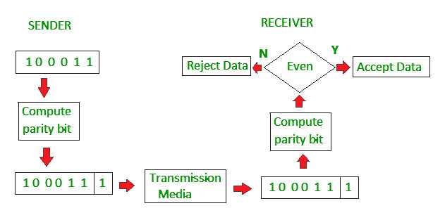
2.
Two-dimensional Parity check
Parity check bits are calculated
for each row, which is equivalent to a simple parity check bit. Parity check
bits are also calculated for all columns, then both are sent along with the
data. At the receiving end these are compared with the parity bits calculated
on the received data.
In Two-Dimensional Parity check, a block of bits is divided into rows, and the redundant row of bits is
added to the whole block. At the receiving end, the parity bits are
compared with the parity bits computed from the received data.
In
an even parity check,
parity bits ensure there are an even number of 1s and 0s in the transmission.
In an odd parity check, there are an odd number of 1s and 0s in the
transmission. 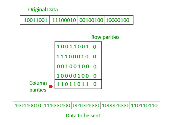

3.
Checksum
A checksum is a value that represents the number of bits in a transmission message and
is used by IT professionals to detect high-level errors within data
transmissions. Prior to transmission, every piece of data or file can be
assigned a checksum value after running a cryptographic hash function.
A sum derived from
the bits of a segment of computer data that is calculated before and after
transmission or storage to assure that the data is free from errors or
tampering
- In
checksum error detection scheme, the data is divided into k segments each
of m bits.
- In
the sender’s end the segments are added using 1’s complement arithmetic to
get the sum. The sum is complemented to get the checksum.
- The
checksum segment is sent along with the data segments.
- At
the receiver’s end, all received segments are added using 1’s complement
arithmetic to get the sum. The sum is complemented.
- If
the result is zero, the received data is accepted; otherwise discarded.
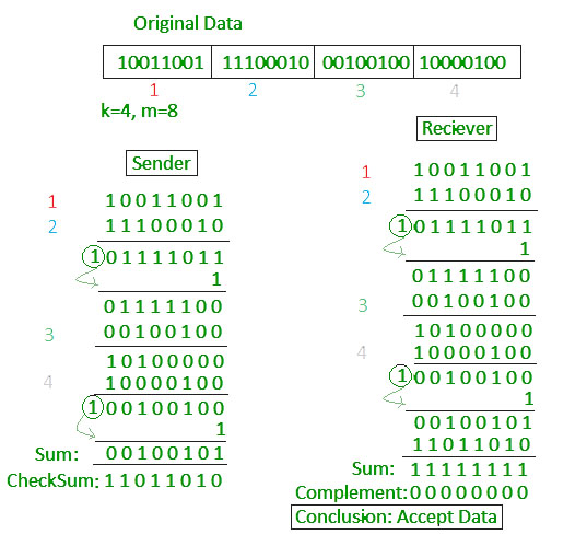
4.
Cyclic redundancy check (CRC)
An error detection technique using
a polynomial to generate a series of two 8-bit block check characters that
represent the entire block of data.
These block check characters are incorporated into the transmission frame and
then checked at the receiving end.
The Cyclic Redundancy Checks (CRC) is the most powerful
method for Error-Detection and Correction. It is given as a kbit message and the transmitter creates an (n – k) bit
sequence called frame check sequence. The out coming frame, including n bits, is precisely divisible by some
fixed number
- Unlike
checksum scheme, which is based on addition, CRC is based on binary
division.
- In
CRC, a sequence of redundant bits, called cyclic redundancy check bits,
are appended to the end of data unit so that the resulting data unit
becomes exactly divisible by a second, predetermined binary number.
- At
the destination, the incoming data unit is divided by the same number. If
at this step there is no remainder, the data unit is assumed to be correct
and is therefore accepted.
- A
remainder indicates that the data unit has been damaged in transit and
therefore must be rejected.
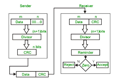
Example : 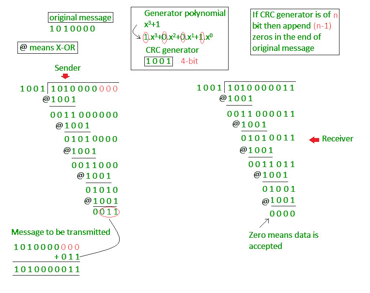
Error Correction
In the digital world,
error correction can be done in two ways:
Backward Error
Correction When the receiver detects an error in the data received, it
requests back the sender to retransmit the data unit.
Forward Error
Correction When the receiver detects some error in the data received, it
executes error-correcting code, which helps it to auto-recover and to correct
some kinds of errors.
The first one, Backward Error Correction, is simple and can only be
efficiently used where retransmitting is not expensive. For example, fiber
optics. But in case of wireless transmission retransmitting may cost too much.
In the latter case, Forward Error Correction is used.
To correct the error in data frame, the receiver must know exactly which
bit in the frame is corrupted. To locate the bit in error, redundant bits are
used as parity bits for error detection.For example, we take ASCII words (7
bits data), then there could be 8 kind of information we need: first seven bits
to tell us which bit is error and one more bit to tell that there is no error.
For m data bits, r redundant bits are used. r bits can provide 2r
combinations of information. In m+r bit codeword, there is possibility that the
r bits themselves may get corrupted. So the number of r bits used must inform
about m+r bit locations plus no-error information, i.e. m+r+1.
![]()
Hamming code is a set of error-correction codes that can
be used to detect and correct the errors that
can occur when the data is moved or stored from the sender to the receiver. It
is a technique developed by R.W. Hamming for
error correction. Redundant
bits – Redundant bits are extra binary bits that are generated and
added to the information-carrying bits of data transfer to ensure that no bits
were lost during the data transfer. The number of redundant bits can be
calculated using the following formula:
2^r ≥ m + r + 1
where, r = redundant bit, m = data bit
Suppose the number of data bits is 7, then the
number of redundant bits can be calculated using: = 2^4 ≥ 7 + 4 + 1 Thus, the
number of redundant bits= 4 Parity bits. A
parity bit is a bit appended to a data of binary bits to ensure that the total
number of 1’s in the data is even or odd. Parity bits are used for error
detection.
There are two types of parity bits:
1.
Even parity bit: In the case of even parity, for a given set
of bits, the number of 1’s are counted. If that count is odd, the parity bit
value is set to 1, making the total count of occurrences of 1’s an even number.
If the total number of 1’s in a given set of bits is already even, the parity
bit’s value is 0.
2.
Odd Parity bit – In the case of odd parity, for a given set of
bits, the number of 1’s are counted. If that count is even, the parity bit
value is set to 1, making the total count of occurrences of 1’s an odd number.
If the total number of 1’s in a given set of bits is already odd, the parity
bit’s value is 0.
General Algorithm of Hamming code:
Hamming Code is simply the use of extra
parity bits to allow the identification of an error.
1.
Write the bit
positions starting from 1 in binary form (1, 10, 11, 100, etc).
2.
All the bit
positions that are a power of 2 are marked as parity bits (1, 2, 4, 8, etc).
3.
All the other bit
positions are marked as data bits.
4.
Each data bit is
included in a unique set of parity bits, as determined its bit position in
binary form. a. Parity bit 1 covers all the
bits positions whose binary representation includes a 1 in the least
significant position (1, 3, 5, 7, 9, 11, etc). b. Parity
bit 2 covers all the bits positions whose binary representation includes a 1 in
the second position from the least significant bit (2, 3, 6,
5.
7, 10, 11,
etc). c. Parity bit 4 covers all the bits positions
whose binary representation includes a 1 in the third position from the least
significant bit (4–7, 12–15, 20–23, etc). d. Parity bit 8
covers all the bits positions whose binary representation includes a 1 in the
fourth position from the least significant bit bits (8–15, 24–31, 40–47,
etc). e. In general, each parity bit covers all bits
where the bitwise AND of the parity position and the bit position is non-zero.
6.
Since we check
for even parity set a parity bit to 1 if the total number of ones in the
positions it checks is odd.
7.
Set a parity bit
to 0 if the total number of ones in the positions it checks is even.

Determining the position of redundant bits – These redundancy bits are placed at positions
that correspond to the power of 2.
As
in the above example:
·
The number of
data bits = 7
·
The number of
redundant bits = 4
·
The total number
of bits = 11
·
The redundant
bits are placed at positions corresponding to power of 2- 1, 2, 4, and 8

·
Suppose the data
to be transmitted is 1011001, the bits will be placed as follows:
Determining
the Parity bits:
·
R1 bit is
calculated using parity check at all the bits positions whose binary
representation includes a 1 in the least significant position. R1: bits 1, 3,
5, 7, 9, 11

·
To find the
redundant bit R1, we check for even parity. Since the total number of 1’s in
all the bit positions corresponding to R1 is an even number the value of R1
(parity bit’s value) = 0
·
R2 bit is
calculated using parity check at all the bits positions whose binary
representationincludes a 1 in the second position from the least significant
bit. R2: bits 2,3,6,7,10,11
·
To find the
redundant bit R2, we check for even parity. Since the total number of 1’s in
all the bit positions corresponding to R2 is odd the value of R2(parity bit’s
value)=1
·
R4 bit is
calculated using parity check at all the bits positions whose binary
representation includes a 1 in the third position from the least significant
bit. R4: bits 4, 5, 6, 7

1.
To find the
redundant bit R4, we check for even parity. Since the total number of 1’s in
all the bit positions corresponding to R4 is odd the value of R4(parity bit’s value)
= 1
1.
R8 bit is
calculated using parity check at all the bits positions whose binary
representationincludes a 1 in the fourth position from the least significant
bit. R8: bit 8,9,10,11
·
To find the
redundant bit R8, we check for even parity. Since the total number of 1’s in
all the bit positions corresponding to R8 is an even number the value of
R8(parity bit’s value)=0. Thus, the data transferred is:
Error detection and correction: Suppose in the
above example the 6th bit is changed from 0 to 1 during data transmission, then
it gives new parity values in the binary number:
The
bits give the binary number 0110 whose decimal representation is 6. Thus, bit 6
contains an error. To correct the error the 6th bit is changed from 1 to 0.
Framing:
Frames are the units of digital transmission,
particularly in computer networks and telecommunications. Frames are comparable
to the packets of energy called photons in the case of light energy. Frame is
continuously used in Time Division Multiplexing process.
Framing is a point-to-point connection between two
computers or devices consists of a wire in which data is transmitted as a
stream of bits. However, these bits must be framed into discernible blocks of
information. Framing is a function of the data link layer. It provides a way
for a sender to transmit a set of bits that are meaningful to the receiver.
Ethernet, token ring, frame relay, and other data link layer technologies have
their own frame structures. Frames have headers that contain information such
as error-checking codes.

At the data link layer, it extracts the message
from the sender and provides it to the receiver by providing the sender’s and
receiver’s addresses. The advantage of using frames is that data is broken up
into recoverable chunks that can easily be checked for corruption.
Problems in Framing –
·
Detecting start of
the frame: When a frame is transmitted,
every station must be able to detect it. Station detects frames by looking out
for a special sequence of bits that marks the beginning of the frame i.e. SFD
(Starting Frame Delimiter).
·
How does the station detect a frame: Every
station listens to link for SFD pattern through a sequential circuit. If SFD is
detected, sequential circuit alerts station. Station checks destination address
to accept or reject frame.
·
Detecting end of
frame: When to stop reading the frame.
Types of framing –
There are two types of framing:
1. Fixed size – The frame
is of fixed size and there is no need to provide boundaries to the frame, the length
of the frame itself acts as a delimiter.
·
Drawback: It suffers from internal fragmentation if the data
size is less than the frame size
·
Solution: Padding
2. Variable size – In this,
there is a need to define the end of the frame as well as the beginning of the
next frame to distinguish. This can be done in two ways:
1.
Length field – We can introduce a length field in the frame
to indicate the length of the frame. Used in Ethernet(802.3). The
problem with this is that sometimes the length field might get corrupted.
2.
End Delimiter (ED)
– We can introduce an ED(pattern) to indicate
the end of the frame. Used in Token Ring. The
problem with this is that ED can occur in the data. This can be solved
by:
Character/Byte
Stuffing:
Used when frames consist
of characters. If data contains ED then, a byte is stuffed into data to
differentiate it from ED.
Let ED = “$”
–> if data contains ‘$’ anywhere, it can be escaped using ‘\O’
character.
–> if data contains ‘\O$’ then, use ‘\O\O\O$'($ is escaped using \O and \O
is escaped using \O).

Disadvantage – It
is very costly and obsolete method.
Bit
Stuffing:
Let ED = 01111 and if data = 01111
–> Sender stuffs a bit to break the pattern
i.e. here appends a 0 in data = 011101.
–> Receiver receives the frame.
–> If data contains 011101, receiver removes the 0 and reads the
data.

Examples –
·
If Data –>
011100011110 and ED –> 0111 then, find data after bit stuffing?
–> 011010001101100
·
If Data –>
110001001 and ED –> 1000 then, find data after bit stuffing?
–> 11001010011
1. FlowControl :
It is an important
function of the Data Link
Layer. It
refers to a set of procedures that tells the sender how much data it can
transmit before waiting for acknowledgement from the
receiver.
PurposeofFlowControl:
Any receiving device has a
limited speed at which it can process incoming data and also a limited amount
of memory to store incoming data. If the source is sending the data at a faster
rate than the capacity of the receiver, there is a possibility of the receiver
being swamped. The receiver will keep loosing some of the frames simply because
they are arriving too quickly and the buffer is also getting filled up.
This will generate waste frames on the network.
Therefore, the receiving device must have some mechanism to inform the sender
to send fewer frames or stop transmission temporarily. In this way, flow
control will control the rate of frame transmission to a value that can be
handled by the receiver.
Example – Stop &
Wait Protocol
2. Error
Control :
The error control function of data link layer detects the errors in transmitted
frames and re-transmit all the erroneous frames.
Purpose of Error Control :
The function of the error control function of the data link layer helps in
dealing with data frames that are damaged in transit, data frames lost in
transit, and the acknowledgement frames that are lost in transmission. The
method used for error control is called Automatic Repeat Request which is used
for the noisy channel.
Example – Stop & Wait ARQ and Sliding
Window ARQ
Difference between Flow Control and Error Control :
|
S.NO. |
Flow control |
Error control |
|
1. |
Flow
control is meant only for the transmission of data from sender to receiver. |
Error
control is meant for the transmission of error free data from sender to
receiver. |
|
2. |
For
Flow control there are two approaches : Feedback-based Flow Control and
Rate-based Flow Control. |
To
detect error in data, the approaches are : Checksum, Cyclic Redundancy Check and Parity Checking. |
|
3. |
It
prevents the loss of data and avoid over running of receive buffers. |
It is
used to detect and correct the error occurred in the code. |
|
4. |
Example
of Flow Control techniques are : Stop&Wait Protocol and Sliding Window
Protocol. |
Example
of Error Control techniques are : Stop&Wait ARQ and Sliding Window ARQ. |
ARQ stands for Automatic Repeat Request
Also
known as Automatic Repeat Query. ARQ is an error-control strategy
used in a two-way communication system. It is a group of error-control
protocols to achieve reliable data transmission over an unreliable source or
service. These protocols reside in Transport Layer and Data Link Layer of the OSI(Open System
Interconnection) model . These protocols are responsible for
automatic retransmission of packets that are found to be corrupted or lost during
the transmission process.
Working
Principle of ARQ
The main function of these protocols is, the sender
receives an acknowledgement from the receiver end implying that the frame or
packet is received correctly before a timeout occurs, timeout is a specific
time period within which the acknowledgement has to be sent by the receiver to
the sender. If a timeout occurs: the sender does not receive the
acknowledgement before the specified time, it is implied that the frame or
packet has been corrupt or lost during the transmission. Accordingly, the
sender retransmits the packet and these protocols ensure that this process is
repeated until the correct packet is transmitted.
Applications
ARQ
protocols have a wide range of applications as they provide reliable
transmissions over unreliable upper sources. These protocols are mainly
functional on shortwave
radio to ensure
reliable delivery of signals.
For the same function of ARQ, there are various applications:
1.
Transmission Control Protocol (TCP)
2.
Specific Service Orientation Protocol:
Error-correction of message signals in ATM networks.
3.
High-Level Data Link protocol.
4.
IBM Binary synchronous Communications
Protocol.
5.
Xmodem : modem file transfer protocol.
Types
There are several types of ways in which these
protocols function in the data link layer :
Stop and wait ARQ is also referred
to as the alternating protocol is a method used in two-way communication
systems to send information between two connected devices (sender and a
receiver). It is referred to as stop and wait ARQ because the function of this
protocol is to send one frame at a time.
After sending a
frame or packet, the sender doesn't send any further packets until it receives
an acknowledgement from the receiver. Moreover, the sender keeps a copy of the
sent packet. After receiving the desired frame, the receiver sends an
acknowledgement. If the acknowledgement does not reach the sender before the
specified time, known as the timeout, the sender sends the same packet again.
The timeout is reset after each frame transmission. The above scenario depicts
a Stop and wait situation, so this control mechanism is termed as Stop and waitARQ.
Go Back-N ARQ:
Go-Back-N ARQ is
a type of the ARQ protocol, in which the sending process continues to send several frames or
packets even without receiving an acknowledgement packet from the receiver. The receiver process keeps track of
the sequence number of the next packet it expects to receive and sends that
sequence number with every acknowledgement to the sender. The receiver will
remove any packet that does not have the desired sequence number it expects and
will resend an acknowledgement for the last correct frame.
There are only
two possibilities that a frame won't match the sequence number: it is either a
duplicated frame of an existing frame or an out-of-order frame that needs to be
sent later, the receiver recognizes this scenario and sends an acknowledgement
signal accordingly.
Once the sender
has sent all of the frames in its window, it will identify that all of the
frames since the first lost frame, and will go back to the sequence
number of the last acknowledgement signal that it received from the
receiver pr and continue the process over again. The only drawback of this type
of system is that it results in sending packets multiple times: if any frame
was lost or found to be corrupted, then that frame and all following frames in
the send window will be re-transmitted.
This protocol is more efficient than Stop and wait ARQ as there is no waiting
time.
- Selective Repeat ARQ/Selective Reject
ARQ:
Selective Repeat
ARQ/Selective Reject ARQ protocol mechanism is similar to the Go-Back-N
protocol mechanism but in Selective Repeat ARQ the sending process continues
even after a frame is found to be corrupt or lost. This is achieved: the receiver
process keeps track of the sequence number of the earliest frame it has not
received and sends the respective sequence number with the acknowledgement
signal. If a frame is not received at the receiver end, the sender continues to
send the succeeding frames until it has emptied its window. once this
error-correction process has been done, the process continues where it left
off. Unlike, Go back-N protocol this does not send a packet multiple
times.
Advantages
of ARQ
- The
Error-detection and correction mechanisms are quite simple compared to the
other techniques.
- A
much simpler decoding equipment can be put to use compared to the other
techniques.
Disadvantages
of ARQ
- A
medium or a channel with a high error rate might cause too much
transmission of the frames or packets of information.
- The
high error rate in the channel might also lead to loss of information,
therefore reducing the efficiency or the productivity of the system.
Multiple access
protocol-
Random Access
Control Protocol
Ø
ALOHA,
Ø
CSMA,
Ø
CSMA/CA
Ø CSMA/CD
ALOHA
ALOHA
is a multiple access protocol for transmission of data via a shared network
channel. It operates in the medium access control sublayer (MAC sublayer) of
the open systems interconnection (OSI) model. Using this protocol, several data
streams originating from multiple nodes are transferred through a multi-point
transmission channel.
1.
Any
station can transmit data to a channel at any time.
2.
It
does not require any carrier sensing.
3.
Collision
and data frames may be lost during the transmission of data through multiple
stations.
4.
Acknowledgment
of the frames exists in Aloha. Hence, there is no collision detection.
5.
It
requires retransmission of data after some random amount of time.
Versions of ALOHA
Protocols
Pure
ALOHA
In
pure ALOHA, the time of transmission is continuous.Whenever a station hasan
available frame, it sends the frame. If there is collision and the frame is
destroyed, the sender waits for a random amount of time before retransmitting
it.
- The total vulnerable time of pure Aloha is 2 *
Tfr.
- Maximum throughput occurs when G = 1/ 2 that is
18.4%.
- Successful transmission of data frame is S = G *
e ^ - 2 G.
Slotted
ALOHA
Slotted
ALOHA reduces the number of collisions and doubles the capacity of pure ALOHA.
The shared channel is divided into a number of discrete time intervals called
slots. A station can transmit only at the beginning of each slot. However,there
can still be collisions if more than one station tries to transmit at the
beginning of the same time slot.
1.
Maximum
throughput occurs in the slotted Aloha when G = 1 that is 37%.
2.
The
probability of successfully transmitting the data frame in the slotted Aloha is
S = G * e ^ - 2 G.
3.
The
total vulnerable time required in slotted Aloha is Tfr.
CSMA
Carrier-sense multiple access with collision
detection (CSMA/CD) is a medium access control (MAC) method used most
notably in early Ethernet
technology for local area networking. It uses carrier-sensing to defer
transmissions until no other stations are transmitting.
t is a carrier sense multiple access based
on media access protocol to sense the traffic on a channel (idle or busy)
before transmitting the data. It means that if the channel is idle, the station
can send data to the channel. Otherwise, it must wait until the channel becomes
idle. Hence, it reduces the chances of a collision on a transmission medium.
CSMA Access Modes
1-Persistent:
In the 1-Persistent mode of
CSMA that defines each node, first sense the shared channel and if the channel
is idle, it immediately sends the data. Else it must wait and keep track of the
status of the channel to be idle and broadcast the frame unconditionally as
soon as the channel is idle.
Non-Persistent:
It is the access mode
of CSMA that defines before transmitting the data, each node must sense the
channel, and if the channel is inactive, it immediately sends the data.
Otherwise, the station must wait for a random time (not continuously), and when
the channel is found to be idle, it transmits the frames.
P-Persistent:
It is the combination
of 1-Persistent and Non-persistent modes. The P-Persistent mode defines that
each node senses the channel, and if the channel is inactive, it sends a frame
with a P probability. If the
data is not transmitted, it waits for a (q = 1-p probability) random time and resumes the
frame with the next time slot.
O- Persistent:
It is an O-persistent method
that defines the superiority of the station before the transmission of the
frame on the shared channel. If it is found that the channel is inactive, each
station waits for its turn to retransmit the data.

CSMA/ CD
It is a carrier
sense multiple access/ collision detection network
protocol to transmit data frames. The CSMA/CD protocol works with a medium
access control layer.
Therefore,
it first senses the shared channel before broadcasting the frames, and if the
channel is idle, it transmits a frame to check whether the transmission was
successful. If the frame is successfully received, the station sends another
frame. If any collision is detected in the CSMA/CD, the station sends a jam/
stop signal to the shared channel to terminate data transmission. After that,
it waits for a random time before sending a frame to a channel.
CSMA/ CA
It is
a carrier sense multiple access/collision avoidance network
protocol for carrier transmission of data frames. It is a protocol that works
with a medium access control layer. When a data frame is sent to a channel, it
receives an acknowledgment to check whether the channel is clear.
If the
station receives only a single (own) acknowledgments, that means the data frame
has been successfully transmitted to the receiver. But if it gets two signals
(its own and one more in which the collision of frames), a collision of the
frame occurs in the shared channel. Detects the collision of the frame when a
sender receives an acknowledgment signal.

Following are the
methods used in the CSMA/ CA to avoid the
collision:
Interframe space:
In this method, the station waits for the
channel to become idle, and if it gets the channel is idle, it does not
immediately send the data. Instead of this, it waits for some time, and this
time period is called the Interframe space
or IFS. However, the IFS time is often used to define the priority of the
station.
Contention window:
In the
Contention window, the total time is divided into different slots. When the
station/ sender is ready to transmit the data frame, it chooses a random slot
number of slots as wait time. If the channel is
still busy, it does not restart the entire process, except that it restarts the
timer only to send data packets when the channel is inactive.
Acknowledgment:
In the
acknowledgment method, the sender station sends the data frame to the shared
channel if the acknowledgment is not received ahead of time.
No comments:
Post a Comment